



Tolérance limite de moulage des goupilles et ajustement pour un arrêt répétable
Mold limit pin tolerance and fit must control two different functions. The pin-to-bore fit controls retention, assembly force, location, and removability. The pin’s working height, seating geometry, surrounding plate dimensions, and contact faces control where the assembly actually stops.
A tight pin diameter alone does not guarantee repeatable stopping. Le trou d’accouplement, seat depth, shoulder thickness, stop-face geometry, and complete axial tolerance stack must also be defined. Within the wider system of Moulage des pièces standard (déduit), this makes the limit pin a component that must be specified from its installed function rather than from catalogue dimensions alone.
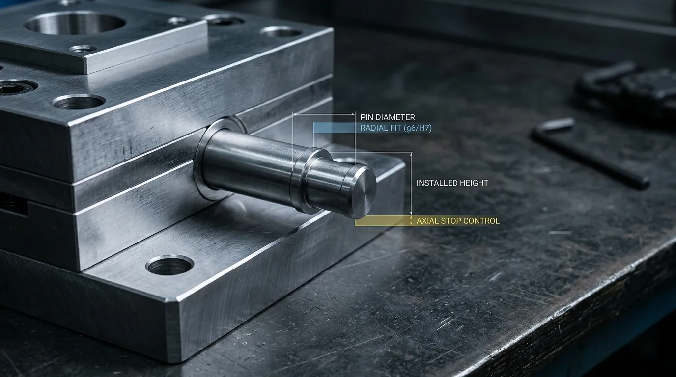
Quelle tolérance et son ajustement contrôlent réellement dans une goupille de limite de moule
The mounting fit and the stopping dimension solve different engineering problems.
Radial fit between the pin body and bore controls:
- À quel point la goupille peut être assemblée facilement
- Que cela puisse bouger ou se balancer à l’intérieur du canon
- Quelle force nécessaire à l’installation
- Si la friction seule la retient
- À quel point il peut être retiré pendant l’entretien
- Est-ce qu’une interférence excessive pourrait endommager la goupille ou la plaque
Axial dimensions and contact geometry control:
- La hauteur de travail installée
- La position finale d’arrêt
- Est-ce que plusieurs broches entrent en contact simultanément
- Comment la charge de contact est répartie
- Si la face d’arrêt est directement opposée à la surface opposée
This distinction matters because a pin can be firmly retained while still producing an incorrect stop position. The opposite is also possible: the working height may be correct, but an excessively loose mounting fit can allow movement, fretting, or inconsistent contact.
Limit Pin, Stop Pin, Guide Pin, or Dowel—Why the Name Matters
Les fournisseurs peuvent utiliser des termes tels que Goupille de limite de moulage, Goupille d’arrêt de moisissure, Goupille d’arrêt, Bouton stop, ou bouton repos for related stopping components. The name alone does not confirm the exact geometry or installed function.
A guide pin normally works with a bushing to control sliding alignment between mold sections. A dowel pin locates stationary components relative to each other. A return pin and an ejector pin perform separate functions within the ejector system.
The assembly drawing should therefore confirm what movement the component limits, which surfaces contact, and how it is retained. For a broader explanation of sliding alignment components, voir Broches et bagues de moulage.
Associer chaque dimension critique à sa fonction
A useful limit pin drawing should identify each critical feature according to what it controls.
| Caractéristiques | Caractéristique de reproduction | Fonction principale | Focus typique de l’inspection |
|---|---|---|---|
| Diamètre extérieur du corps de la goupille | Alésage de montage | Radial fit, location, and possible frictional retention | Diamètre aux positions et orientations pertinentes |
| Alésage de montage | Corps à goupille | Plage de dégagement ou d’interférence | Bore size, Géométrie, Condition de la surface, and lead-in |
| Durée des engagements | Longueur du forage | Comportement de rétention et soutien contre le balancement | Longueur effective du contact |
| Épaisseur de l’épaule ou de la tête | Surface de sièges à assises | Position axiale de la goupille | Épaisseur et condition de la face de l’assise |
| Profondeur de l’assise ou de l’assise | Épaule ou tête épinglée | Hauteur de travail installée | Profondeur à partir du datum fonctionnel |
| Hauteur de travail fonctionnelle | Surface d’arrêt opposée | Position finale d’arrêt | Hauteur à partir du datum de sièges installé |
| Longueur totale de la goupille | Enveloppe d’assemblage | Emballage et mise en liquide au sein de l’assemblage | Dimension globale où la fonction était pertinente |
| Diamètre de la face d’arrêt | Plaque opposée ou surface d’arrêt | Aire de contact et répartition locale de la pression | Diamètre, Platitude, Usure, and damage |
| Position de la face de l’arrêt | Face de siège et axe de goupille | Contact complet et carré | Parallélisme ou perpendiculité lorsque nécessaire |
The pin body tolerance should never be reviewed in isolation. A nominal 10 mm pin, par exemple, does not reveal whether the assembly will have clearance or interference unless the accepted bore limits are also known.
La longueur totale n’est pas toujours la dimension fonctionnelle d’arrêt
The functional dimension is the distance from the surface that seats the pin to the surface that makes the stop contact.
For a headed or shouldered pin, this may differ from the pin’s full end-to-end length. For a counterbored installation, the seat depth also changes the installed projection. A screw-retained stop button may use another surface as its axial reference.
The drawing should dimension the working height directly from defined functional datums whenever possible. Controlling only the overall length can leave the true stopping dimension dependent on several uncontrolled intermediate features.
How to Choose Clearance, Transition, or Interference Fit
There is no universal fit class for every mold limit pin. The appropriate choice depends on how the pin is retained, whether it must be replaceable, the mating materials, engagement length, Température, available installation force, and expected contact conditions.
Le Système de tolérance ISO 286 provides a standardized framework for expressing hole and shaft tolerance zones. It does not prescribe one fit for all mold stop applications.
| Type d’ajustement | Principal avantage | Limitation principale | Direction appropriée |
| Ajustement de dégagement | Assemblage et retrait faciles | Does not provide frictional retention; movement may occur without another locating or retaining feature | Utilisation lorsque la disponibilité est importante et que la conservation est assurée séparément |
| Ajustement de transition | Peut fournir un emplacement proche avec une faible garde au sol ou des interférences légères | Les assemblages réels peuvent varier entre jeu et interférence | Utilisation lorsque l’emplacement contrôlé est nécessaire mais que le pressage important est indésirable |
| Ajustement par interférence | Assure la rétention par friction et limite le mouvement radial | Higher installation force, possible bore stress, difficult removal, and risk of plate damage | Use only after checking material, engagement length, assembly method, et besoins de maintenance |
| Ajustement mécaniquement maintenu | Retention comes from a shoulder, screw, Tête, Fil, or other positive feature | Nécessite une géométrie et un accès supplémentaires | Utile lorsque le concepteur souhaite un emplacement contrôlé avec un retrait prévisible |
A stronger interference fit is not automatically better. Excessive interference can increase assembly force, scrape surfaces, distort a thin surrounding section, or make replacement difficult. Too little retention can allow the pin to shift or fret inside the bore.
The design decision should answer five questions:
- Must the pin be removable without remachining the plate?
- Is radial location provided by the body fit or by another feature?
- Does friction retain the pin, or is there a shoulder, Tête, screw, or thread?
- What engagement length and plate material surround the pin?
- Can the specified fit be assembled and inspected consistently?
Calculer l’ajustement assemblé dans le pire des cas
Use the actual accepted limits of the pin and bore, not only their nominal sizes.
Let:
- (H_{max}) = largest accepted bore
- (H_{min}) = smallest accepted bore
- (P_{max}) = largest accepted pin
- (P_{min}) = smallest accepted pin
Alors:
Garde maximale
[
C_{max} = H_{max} - P_{min}
]
Garde minimale
[
C_{min} = H_{min} - P_{max}
]
A positive result indicates clearance. A negative result indicates interference.
Par exemple, suppose a hypothetical design allows a bore from 10.000 to 10.012 mm and a pin from 9.996 to 10.004 mm.
- Maximum clearance = 10.012 − 9.996 = 0.016 mm
- Minimum clearance = 10.000 − 10.004 = −0.004 mm
This is a transition condition because accepted parts could assemble with either clearance or interference. The designer must confirm that both extremes are acceptable.
Quand la capacité à retirer compte plus que la rétention maximale
A limit pin may become a service item if its contact face wears, the mold is rebuilt, or the stopping position must be adjusted. A heavy press fit can make replacement more difficult and may damage the mounting bore during removal.
Where serviceability matters, a controlled clearance or transition fit combined with positive retention may be more practical than relying only on interference. The correct choice depends on the assembly layout and should be established before the pin and bore tolerances are finalized.
Construisez la pile de tolérance axiale pour la position d’arrêt
The final stopping position is the result of every dimension between the fixed seating datum and the moving contact surface. Tightening the pin-length tolerance cannot compensate for an uncontrolled seat or plate stack.
A practical stack analysis follows this sequence:
- Identify the fixed functional datum.
This may be the backing plate surface, counterbore floor, shoulder seat, or another stable reference. - Identify the final contact surface.
Define exactly which pin face and opposing plate face establish the stop. - List every dimension in the datum chain.
Include the pin working height, shoulder thickness, counterbore depth, Épaisseur de la plaque, spacer thickness, and any other feature that changes the installed projection. - Assign direction to each dimension.
Some dimensions increase the projection; others reduce it. - Calculate the accepted extreme positions.
Use the maximum and minimum limits to determine the total possible stop-position range. - Compare the stack with the functional allowance.
If the stack is too wide, improve the dimensions that contribute most strongly rather than tightening every feature without reason.
A simplified symbolic stack could be written as:
[
S = W - D + T
]
Où:
- (S) = installed stop position
- (W) = pin working height
- (D) = seat or counterbore depth
- (T) = any additional plate or spacer dimension in the functional chain
The actual equation must follow the real assembly configuration.
Définir la hauteur de travail à partir des données fonctionnelles
The working height should be measured from the surface that fully seats the component to the face that makes stop contact. Those surfaces should also guide the drawing datum system.
Direct functional dimensioning is usually clearer than a long chain of dimensions. If the stop position depends on the difference between overall length, Épaisseur de la tête, and seat depth, each tolerance contributes to the final variation.
Le Norme ASME Y14.5 de dimensionnement et de tolérance provides standardized rules for defining datums and geometric relationships on engineering drawings. The selected controls should reflect the actual stopping function rather than being added automatically.
Correspondre plusieurs quilles pour un contact simultané
Several limit pins with the same nominal length may not contact simultaneously. Relative working-height differences, seat-depth variation, plate flatness, and stop-face geometry can cause one pin to touch first.
The first pin to contact may receive a disproportionate share of the initial load. Typical evidence includes:
- Une marque de témoin forte sur une épingle et peu de contact sur les autres
- Les endentations ou les endentations se concentrent à un seul endroit
- Balancement ou inclinaison lorsque la plaque mobile atteint l’arrêt
- Changement de schéma de contact après l’installation d’une goupille de remplacement
Where simultaneous contact matters, specify how closely the pins must be matched as a set. The assembly inspection should also verify the contact pattern rather than accepting each loose pin only by its individual length.
Control Geometry, Sièges, and Surface Condition
Size tolerance alone does not ensure complete seating or square contact.
The following controls may be relevant:
- Stop-face flatness: Helps create consistent face contact.
- Parallelism: May be needed between the seating face and stop face.
- Perpendiculité: May relate the pin axis to a shoulder or contact face.
- Poste: May be needed where pin location affects engagement with a specific contact area.
- Bore geometry: Rondeur, Droiture, and surface condition can affect assembly even when measured bore size appears acceptable.
- Finition de surface: Influences friction during assembly, seating consistency, Mesure, and contact behavior.
Meules, Débris, damaged counterbores, raised edges, or incomplete seating can change the installed height. A dimensionally correct pin may therefore produce the wrong stopping position after assembly.
Coating or surface-treatment thickness must also be considered when it changes the final pin diameter or working height. Dimensions should clearly apply to the correct manufacturing condition.
Use GD&T Only Where the Functional Relationship Requires It
Geometric dimensioning and tolerancing should protect a defined function.
Par exemple:
- Apply flatness when the stop face must make controlled area contact.
- Apply parallelism when the stop face must remain parallel to the seating datum.
- Apply perpendicularity when the pin axis must remain square to a functional face.
- Apply position when the pin must contact a defined area or align with another assembly feature.
Avoid adding tight geometric controls without a measurement plan. A callout has little value when the supplier or inspection team cannot verify it reliably.
Inspect the Pin, Alésage, and Installed Stop
Inspection should follow the functional chain rather than checking only the loose component.
- Clean the pin, Calibre, seating face, and measuring surfaces.
- Allow the parts and measuring equipment to stabilize.
- Measure the pin body at relevant positions and orientations.
- Verify the mating bore using a suitable bore gauge, pin gauge, or other controlled method.
- Check the shoulder or head thickness and seat depth.
- Measure the working height from the functional seating datum.
- Inspect specified stop-face and seating geometry.
- Assemble the pin and confirm complete seating.
- Measure the installed stop position or final plate position.
- Check contact patterns when several pins share the stop.
The measuring method must have sufficient resolution and controlled uncertainty for the specified tolerance. A narrow drawing tolerance cannot be accepted confidently with an instrument or process that cannot resolve the difference between conforming and nonconforming parts.
Pour des considérations plus larges concernant les fournisseurs et la qualité Pièces de moule de précision, the inspection plan should still return to the specific limit-pin features that control the stop.
Contrôler la température avant d’accepter des mesures précises
Dimensional measurements are sensitive to temperature because the pin, Plaque, and measuring equipment expand or contract. Industrial dimensional measurements conventionally use 20°C as the reference temperature, Comme expliqué par le Institut national des normes et de la technologie.
For close tolerances:
- Stabilize the pin and plate before measurement.
- Avoid measuring a warm part immediately after grinding or handling.
- Record temperature when it can materially affect the result.
- Include temperature-related uncertainty where required by the tolerance.
Inspect the Installed Assembly, Not Only the Loose Pin
Loose-part inspection confirms component dimensions. It does not prove that the assembled stop is correct.
After installation, Vérifier:
- Contact total avec la surface des sièges
- Hauteur de travail installée
- Position finale arrêtée de la plaque mobile
- Contact à travers chaque broche de limite prévue
- Absence de balancement ou de fissures visibles
- No change caused by debris, meules, or installation damage
Assembly-level inspection is especially important when the stopping position depends on several plates and seated features.
Diagnostiquer les échecs courants d’ajustement et de tolérance
| Symptôme | Possible Cause | Contrôle d’inspection | Corrective Direction |
| Mouves de quilles ou pierres dans le canon | Excessive clearance, bore wear, short engagement, or missing retention | Measure pin and bore limits; inspect engagement length and retention feature | Corrigez l’ajustement ou ajoutez une rétention positive appropriée |
| La force d’installation est excessive | Too much interference, damaged lead-in, meules, rough finish, ou désalignement | Vérifiez les interférences réelles et inspectez l’entrée et les surfaces du forage | Correct the bore or fit specification; do not force assembly |
| La quille ne s’installera pas complètement | Débris, meules, damaged counterbore, incorrect shoulder geometry, or trapped obstruction | Inspectez le siège et comparez la hauteur installée avec le dessin | Nettoyez ou réparez la structure de la selle et vérifiez la géométrie |
| La position de la butée varie après remplacement | Replacement working height differs, seat damage, or tolerance stack was not controlled | Comparez les hauteurs de travail fonctionnelles et inspectez le siège | Spécifier la hauteur de travail interchangeable à partir des datums fonctionnels |
| Une épingle montre de fortes marques de témoin | Unequal pin heights, seat-depth variation, plate distortion, or poor parallelism | Vérifiez les hauteurs et les motifs de contact correspondants | Corrigez la géométrie relative de la pile ou du contact |
| Un entame ou une indentation apparaît sur la face de la butée | Concentrated contact, insufficient area, excessive impact, or unsuitable material pairing | Inspect contact area, surface geometry, hardness condition, et répartition des charges | Examinez la conception du contact et l’état du matériau |
| L’alésage montre des frettes ou des polissages | Microdéplacement sous charge | Inspect fit, Rétention, and signs of cyclic movement | Améliorer la localisation ou la rétention après avoir vérifié les besoins de maintenance |
| La plaque est endommagée lors du retrait | Interférence excessive ou accès à l’élimination inadéquat | Comparez l’ajustement réel avec les besoins d’entretien | Utiliser une stratégie de rétention plus efficace dans les conceptions futures |
Replacement should be based on condition, Changement dimensionnel, Dommages par contact, or loss of function—not a universal cycle count.
Transformez l’exigence fonctionnelle en un dessin ou une demande de propositions
A useful RFQ should include the mating assembly, not only a standalone pin sketch.
Fournir:
- Diamètre nominal de la broche et limites acceptées
- Diamètre nominal du forage d’accouplement et limites acceptées
- Ajustement requis ou plage d’interférence/dégagement acceptable
- Hauteur de travail fonctionnelle et références
- La longueur totale était pertinente séparément
- Shoulder, Tête, Fil, screw, ou détails de conservation
- Durée d’engagement effective
- Matériaux de plaque et conditions de traitement thermique pertinentes
- Diamètre de la face d’arrêt et contrôles géométriques requis
- Dimensions du siège ou du canon
- Les exigences de finition de surface ou de revêtement étaient fonctionnelles
- Quantité et si les quilles doivent être associées en ensemble
- Exigences d’interchangeabilité des pièces de rechange
- Matériel requis, Dureté, and dimensional reports
- Dessin d’assemblage ou section montrant la fonction d’arrêt
The supplier should also know whether the component must be removable and whether final dimensions apply before or after heat treatment or coating.
Ce que les tolérances publiées par SunshinePro peuvent — et ne peuvent pas — vous dire
SunshinePro Mold Limit Pin product page lists S45C material, an outer-diameter tolerance of −0.01 to −0.2 with precision grinding, a length tolerance of +0.1 to +0.5, and product hardness of 15–17 HRC. The page also states that standard sizes and non-standard size customization are available.
These published values describe the listed product, but they do not independently define:
- L’ajustement résultant de la goupille au canon
- Le dégagement ou l’interférence autorisé
- La tolérance fonctionnelle de hauteur de travail
- La combinaison de tolérance du siège et des plaques
- La géométrie de contact requise
- L’adéquation du composant à une charge spécifique ou à un plan de maintenance
A complete inquiry should therefore include the mating bore, functional datums, installed working height, Méthode de rétention, and assembly context. SunshinePro describes a workflow that includes drawing submission, Revue de conception, citation, Traitement, and quality inspection.
Once those requirements are defined, Tu peux Soumettre la goupille limite et le dessin de l’assemblage d’accouplement for review or quotation. This gives the supplier enough information to evaluate the complete stopping function rather than matching only a pin diameter and overall length.
Partager:


Écrit par Sunshine
Au soleil, Nous sommes un fabricant et fournisseur professionnel de composants de moule de précision, proposant une large gamme de produits pour les applications de stampage et de moulage par injection. Notre objectif principal est le poinçage des coins, Goupilles et manchons d’éjection, et poteaux guides et bagues. Avec un usinage CNC avancé, Contrôle qualité strict, et de fortes capacités de production, Nous garantissons une fiabilité, Pièces de haute précision, ainsi que des composants standards en stock pour un approvisionnement mondial rapide et efficace.
ACTUALITÉS
OBTENIR UN SERVICE
Avec des pièces de qualité adaptées à tous les budgets et un personnel accueillant formé pour rendre votre visite informative et sans tracas.
