



Inspection de l’usure des goupilles de limitation de moisissure: Mesures et indices de défaillance
A proper mold limit pin wear inspection combines visual evidence with controlled dimensional measurements. A polished contact face alone does not prove that the pin is damaged, while a pin that appears clean may still have lost diameter, effective height, or straightness.
The pin should be compared with a controlled drawing, an approved inspection record, a qualified spare, or a documented historical baseline. There is no universal wear allowance or replacement cycle that applies to every mold.
Les broches de limite font partie du système plus large de remplaçables Moulage des pièces standard (déduit). This guide focuses only on how to inspect their wear, interpret failure clues, and document the next technical action.
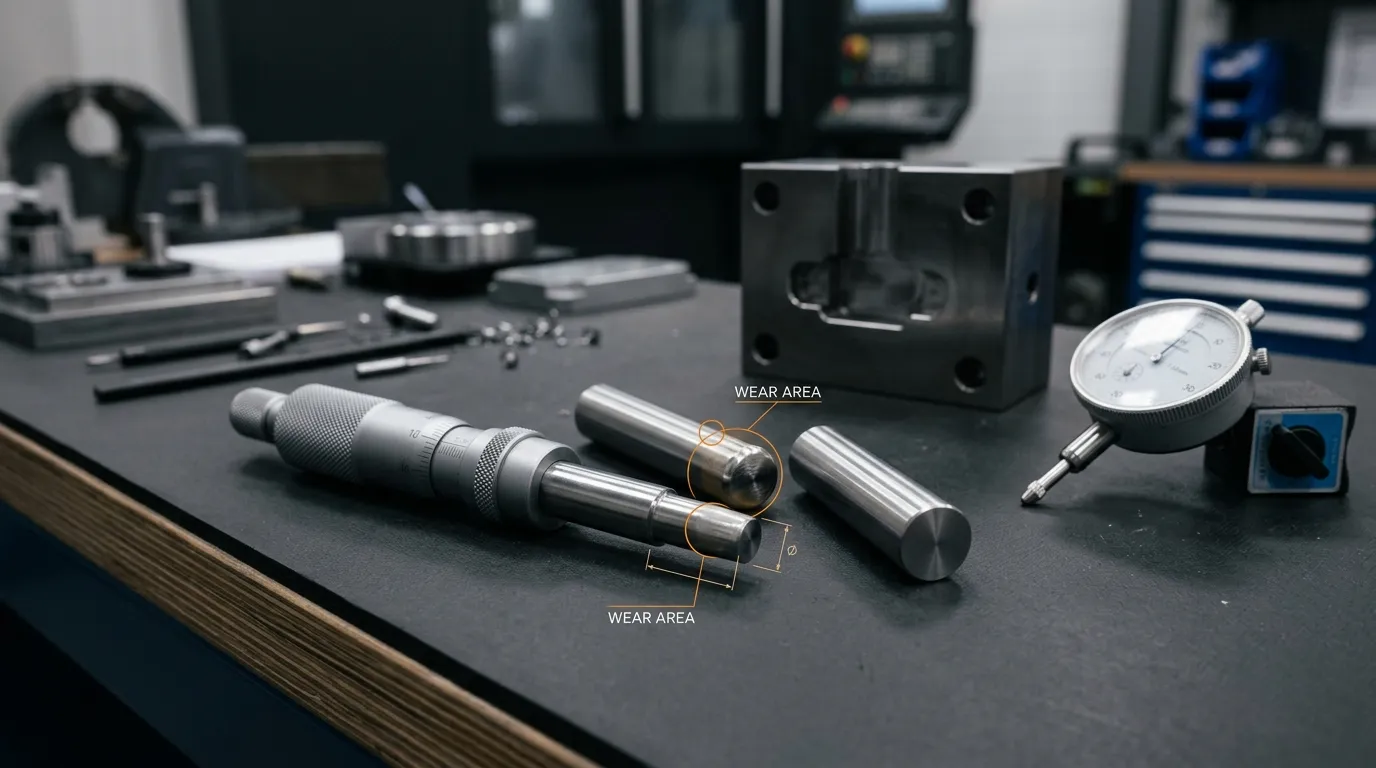
Établir une référence d’inspection sûre et valide
Before opening, removing, or measuring a limit pin, isolate the molding machine and control all stored energy according to the procedures that apply at the facility. Stored hydraulic pressure, Sources, suspended mold sections, gravity, and moving plates can remain hazardous even after the machine has stopped.
Pour les lieux de travail américains, OSHA 29 CFR 1910.147 provides requirements for controlling hazardous energy during servicing and maintenance. Other countries and regions have their own requirements, so the applicable local procedure must control the work.
Before measurement:
- Support the mold and any movable assembly securely.
- Record the pin’s position before removal.
- Photograph visible damage before cleaning it away.
- Enlever l’huile, loose debris, corrosion residue, and dirt from measuring surfaces.
- Check for burrs that could distort the reading.
- Allow the pin and reference equipment to reach a stable measurement condition.
- Confirm which drawing revision or baseline will be used.
Confirm the Pin by Function, Not Name Alone
Les conditions Broche de limite, Goupille d’arrêt, et Goupille d’arrêt may describe similar travel-limiting functions, but naming is not consistent across mold designs and suppliers.
Identify the component by asking:
- Which plate or assembly does it stop?
- Where is its contact face?
- Which surface does it contact at the end of movement?
- Does it carry stopping load, guide movement, return a plate, eject a part, or locate an assembly?
A return pin, ejector pin, guide pin, dowel, or locating pin should not be assessed using a limit-pin procedure simply because it has a similar cylindrical shape.
Choisissez la référence avant de prendre des mesures
A measured value has little meaning until it is compared with a valid requirement. Use the strongest available reference in this order:
- Dessin contrôlé de composants ou moules
- Spécification OEM ou norme d’inspection approuvée
- Rapport d’inspection approuvé précédemment
- Nouvelle pièce de secours qualifiée
- Mesures historiques à partir de la même position de goupille
- Comparaison relative avec des broches correspondantes provenant du même ensemble
Confirm the units, datum surfaces, Tolérances, and drawing revision. A nominal length measured from the wrong shoulder or reference face may produce a precise but useless result.
When a result is close to an acceptance limit, measurement uncertainty also matters. ISO 14253-1:2017 addresses how specification limits and measurement uncertainty affect conformity decisions.
Manufacturing tolerances listed on a supplier’s product page should not automatically be treated as service-wear limits. New-part acceptance and continued-service acceptance are different engineering decisions.
Inspectez la goupille et son système de contact avant de mesurer
Begin with a systematic visual examination. Use strong lighting and magnification where needed, but inspect the surrounding components as well as the pin itself.
Check these areas:
- Contact ou face d’arrêt
- Bord extérieur de la face d’arrêt
- Tige cylindrique
- Transitions diamétriques
- Épaule ou tête
- Fonctionnalités de thread et de rétention
- Surface de sièges
- Surface d’arrêt correspondante dans le moule
- D’autres broches qui partagent la même charge d’arrêt
Look for polishing, flattened areas, mushrooming, Score, metal transfer, Pitting, Corrosion, fissures, Bords ébréchés, Dégâts du filetage, and fretting around retained interfaces.
The mating stop surface deserves equal attention. An indentation, Meule, embedded particle, or worn pocket can change the functional stopping position even when the pin itself remains close to its original length.
Séparer le polissage normal des témoins des dommages anormaux
A centered and stable polished witness mark may simply show where normal contact occurs. It becomes more concerning when the pattern changes shape, moves toward one edge, or differs significantly between pins in the same set.
| Observation | Interprétation initiale |
|---|---|
| Centered, even polishing | Peut indiquer un contact normal et équilibré |
| Marquage unilatéral ou diagonal | Possible misalignment, unequal height, ou chargement latéral |
| Face d’arrêt aplatie | Impact répété ou charge concentrée |
| Bord en champignon | Déformation plastique à la face de contact |
| Notation longitudinale | Abrasive debris, Contact coulissant, ou désalignement |
| Métal étalé ou micro | Éventuellement de galles ou d’usure par adhésif |
| Fissures ou bords ébréchés | Dommages structurels nécessitant une escalade immédiate |
| Rouille ou piqûres | Perte de matériau liée à la corrosion ou mauvaises conditions de stockage |
These observations are clues, not final diagnoses. One-sided wear, par exemple, may come from a bent pin, unequal pin heights, Usure du système de guidage, a damaged seat, or an uneven mating surface.
Measure Diameter Wear, Effilage, and Ovality
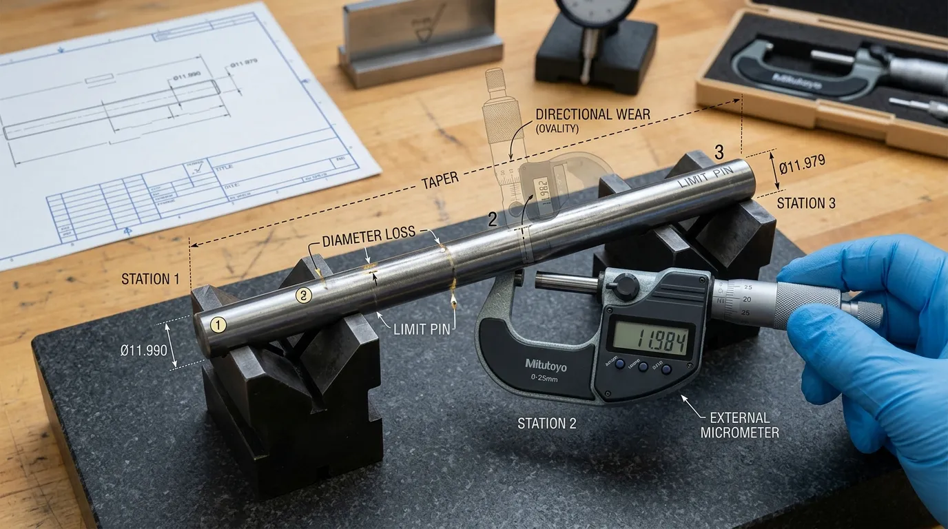
A single diameter reading cannot describe the complete wear condition of a limit pin. Measurements should be taken at repeatable axial locations and in more than one rotational orientation.
An external micrometer is usually more suitable than a caliper when small diameter changes must be evaluated. ISO 3611:2023 defines design and metrological characteristics for external micrometers. Calipers are useful for preliminary checks, but their capability must match the tolerance and expected amount of wear. Their general metrological characteristics are covered by ISO 13385-1:2019.
A practical measurement sequence is:
- Mark the measurement locations along the shank.
- Measure near the upper working area.
- Measure near the centre.
- Measure near the lower working area or seat, where accessible.
- At each location, take readings in at least two rotational orientations.
- Record the position and orientation of every reading.
- Compare the results with the drawing, spare, baseline, and corresponding pins.
This pattern helps separate several conditions:
- Diameter loss: The measured diameter is smaller than the approved reference.
- Effilage: Diameter changes progressively along the pin’s length.
- Ovalité: Readings differ when the pin is rotated at the same axial position.
- Tenue locale: One short area shows greater loss than the rest of the shank.
Directional diameter loss often supports an investigation into side loading or alignment. Progressive axial wear may indicate contact in a specific working zone rather than uniform material loss.
Do not assign a universal rejection value. The acceptable difference depends on the controlled design, Ajusté, Charge, and function of the individual mold.
Check Length, Protrusion, and Effective Stop Height
Overall length is not always the most important axial measurement. The functional dimension may be free length, installed protrusion, shoulder-to-face distance, recess depth, or assembled stop height.
First identify the dimension that actually controls plate movement. Then check:
- Longueur totale ou libre
- Déformation face de contact
- Protubérance installée
- Sièges en épaule
- Thread engagement
- Profondeur des sièges
- Condition de surface d’accouplement
- Hauteur relative des broches correspondantes
A pin may measure correctly after removal but still sit too low because of debris under the shoulder, Dégâts du filetage, seat wear, or an incorrect replacement geometry. The opposite can also occur: the pin may appear shortened when the real loss is an indentation in the opposing stop surface.
Use a height gauge, depth micrometer, height micrometer, or another suitable setup based on the controlled datum and accessibility. The setup must be rigid enough to produce repeatable results.
Comparez toutes les broches qui partagent la charge d’arrêt
Several limit pins may work together to stop the same moving plate. Their effective heights should be compared because one high pin can contact first and carry more load than the others.
Check whether:
- Contact patterns appear on all corresponding pins.
- Protrusion or effective height is consistent.
- One pin has a larger polished or deformed area.
- One position shows deeper indentation on the mating surface.
- A previously replaced pin differs from the remaining set.
- One pin contacts before the plate becomes parallel.
Replacing only the visibly damaged pin may not solve the problem if the set has unequal heights or if another component caused the load imbalance.
Check Runout, Flexion, and Straightness
A pin subjected to side loading, Collision, or severe misalignment may bend without showing major diameter loss.
Where the geometry permits, support the clean pin on suitable datum surfaces or V-blocks and use a dial indicator to measure variation during rotation. Record the indicator position and support arrangement so the test can be repeated.
Before accepting the result, vérifier pour:
- Meules sous les points de support
- De la saleté sur les blocs en V
- Surfaces cylindriques endommagées
- Épaules irrégulières
- Mauvais alignement des indicateurs
- Force de mesure excessive
- Déplacement du support
Runout, Droiture, and coaxiality are related but not interchangeable terms. ISO 1101:2017 provides the geometrical tolerancing framework for form, Orientation, Emplacement, et runout. Straightness terminology is further defined in ISO 12780-1:2011.
The total indicated variation from a workshop setup should not automatically be treated as the drawing’s straightness error. It is an inspection result that must be interpreted against the specified geometry and measurement method.
When bending or directional wear is found, inspect the mold’s alignment system. Usé Broches et bagues de moulage can allow plate movement that places abnormal side load on a limit pin.
Interprétez les schémas d’usure sans aller directement à la cause
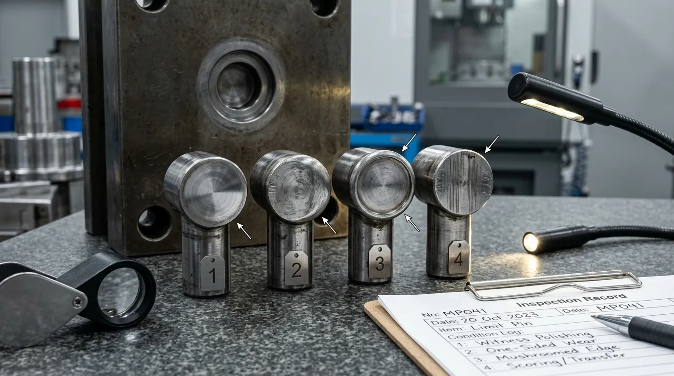
Use each wear pattern to guide further inspection rather than treating it as proof.
| Indice d’échec | Causes possibles | Vérifications de confirmation | Réponse immédiate |
| Marque de témoin à sens unique | Désalignement, unequal pin height, angled mating surface | Compare matched-pin heights, État du guide, Parallélisme de plaques | Poursuivez le diagnostic avant de remplacer la goupille |
| Visage aplati ou en champignon | Impact répété, overtravel, surface de contact insuffisante, unequal loading | Check effective height, stroke, Surface d’accouplement, other pins | Mesurer la perte axiale et augmenter si la déformation est active |
| Notation longitudinale | Débris, Usure abrasive, Contact coulissant, Mauvais alignement | Inspect bore or surrounding surface, Contamination, Système de guidage | Éliminer la contamination et évaluer la perte de diamètre |
| Gallage ou transfert de métaux | Fort frottement, Usure par adhésif, poor surface compatibility | Look for transferred material, heat discoloration, surface d’accouplement rugueuse | Arrêtez les dégâts continus et examinez la paire de contacts |
| Local diameter loss | Usure par contact concentré ou abrasive | Diamètre de la carte à plusieurs positions axiales | Comparer avec le dessin et les données historiques |
| Réduction ou ovalité | Directional wear, Charge latérale, uneven support | Rotate measurements, inspect alignment and seating | Déterminez si l’usure est stable ou progresse |
| Trop de runout | Flexion, Collision, Chargement latéral | Repeat indicator setup, inspect guide system and plate movement | Examen technique avant réutilisation |
| Corrosion ou piqûres | Humidité, Exposition chimique, poor storage | Examinez les composants et les conditions de stockage à proximité | Évaluer la profondeur et l’effet structurel |
| Fissures ou bords ébréchés | Impact fatigue, Surcharge, material damage | Inspectez avec un grossissement approprié ou une méthode NDT approuvée | Retirer du service et escalader |
| Dommages au fil ou à l’épaule | Loosening, improper seating, repeated movement | Check seat, Engagements, retention and installed height | Corrigez le problème de rétention avant le remplacement |
Abnormal sound, Stuck, plate travel changes, Flash, or mismatch can justify an unscheduled inspection. They do not independently prove that the limit pin is the failed component.
Decide Whether to Continue, Moniteur, Remplacer, or Escalate
The final decision should combine dimensional results, visible condition, functional evidence, and the approved acceptance criteria.
| Décision | Condition appropriée |
| Maintien du service | Measurements meet approved criteria, contact is stable, no structural damage is present, and associated components are acceptable |
| Moniteur | Minor measurable change is permitted, the condition is stable, and a documented reinspection plan is approved |
| Remplacer | The pin is outside its controlled specification, has unacceptable height variation, Déformation sévère, damaged retention features, craquelement, Ébréchage, or active galling |
| Revue technique | No valid specification exists, results conflict, uncertainty is too high, damage keeps returning, or system-level misalignment is suspected |
A pin should not be polished or reground automatically. Material removal can change its effective length, stop height, Synchronisation des contacts, et répartition des charges. Serviceability depends on the component’s function and approved dimensional limits.
Generic cycle-count recommendations are also unreliable. Two molds using similar pins may create very different impact loads, alignment conditions, contamination exposure, and maintenance histories.
Enregistrez l’inspection et évitez les erreurs courantes de mesure
A useful inspection record should include:
- Identification de la moisissure
- Position du clou
- Numéro de dessin et révision
- Référence utilisée
- Instrument de mesure et résolution
- Emplacements de mesure
- Valeurs et unités enregistrées
- Photographies
- Condition de surface d’accouplement
- Condition des broches correspondantes
- Symptômes opératoires pertinents
- Final disposition
- Déclencheur de réinspection ou intervalle approuvé
Consistent records make it possible to see whether wear is stable or accelerating.
Common errors include:
- Measuring through oil, Tranquillité, Terre, or burrs
- Mesurer un composant chaud par rapport aux données de référence à température ambiante
- Prendre une seule lecture du diamètre
- Changement de lieu de mesure entre les inspections
- Utiliser un pied à coulisse lorsque la résolution est plus élevée
- Confondre la sortie indiquée avec la rectitude définie par le dessin
- Ignorer la selle ou la surface d’arrêt d’accouplement
- Comparaison des broches qui ne sont pas fonctionnellement appariées
- Enlever les dégâts avant de le photographier
- Considérer les tolérances de fabrication des pièces neuves comme des limites d’usure de service
Broader tolerance, Acier, and inspection considerations for Pièces de moule de précision can support replacement planning, but the used pin must still be judged against its own controlled requirements.
Préparez les données nécessaires pour un code PIN de remplacement ou personnalisé
When inspection confirms that a replacement is required, prepare enough information to reproduce the functional geometry rather than sending only the worn component’s current dimensions.
Fournir:
- Dessin contrôlé ou esquisse dimensionnée
- Dimensions nominales
- Dimensions mesurées de l’usure
- Hauteur de butée fonctionnelle
- Géométrie des faces de contact
- Épaule, Tête, Fil, and seat details
- Material and hardness requirement, where known
- Quantité
- Exigences pour ensembles appariés
- Photographies de la goupille et de la surface d’accouplement
- Résultats de l’inspection
- Cause probable de l’échec
- Documentation d’inspection requise
SunshinePro liste les standards et les non-standards Goupille de limite de moulage options, including customization from dimensional requirements. Its published product information identifies S45C/45# steel, Rectification de précision, threaded construction, Traitement thermique sous vide, and a stated hardness of 15–17 HRC for that listed product.
Those details are product-specific. They should not be assumed to apply to every existing pin or used as universal replacement criteria.
Replacing the pin without correcting damaged seating, an indented stop surface, unequal matched heights, or alignment problems can cause the new component to fail in the same way. After the cause and required geometry are documented, the drawing, Mesures, and photographs can be submitted through SunshinePro’s Page de contact for a standard or custom replacement discussion.
Partager:


Écrit par Sunshine
Au soleil, Nous sommes un fabricant et fournisseur professionnel de composants de moule de précision, proposant une large gamme de produits pour les applications de stampage et de moulage par injection. Notre objectif principal est le poinçage des coins, Goupilles et manchons d’éjection, et poteaux guides et bagues. Avec un usinage CNC avancé, Contrôle qualité strict, et de fortes capacités de production, Nous garantissons une fiabilité, Pièces de haute précision, ainsi que des composants standards en stock pour un approvisionnement mondial rapide et efficace.
ACTUALITÉS
OBTENIR UN SERVICE
Avec des pièces de qualité adaptées à tous les budgets et un personnel accueillant formé pour rendre votre visite informative et sans tracas.
