



Limites d’usure et d’inspection de l’alésage de la puce des tablettes
Tablet die bore wear measurement requires more than checking the internal surface for a visible ring. A wear ring can identify a suspect area, but it cannot show how much the bore has enlarged, whether the change is uniform, or whether the die remains within an approved operating limit.
A reliable inspection combines visual examination with controlled dimensional measurements at defined depths and orientations. The results should be compared with the correct tooling drawing, setting reference, or new-tool baseline. Acceptable wear must then be judged against product-specific warning and rejection limits—not a universal value taken from another tooling set.
For broader context on how dies interact with upper and lower punches, voir Types d’outils de presse à tablette. This guide focuses specifically on measuring internal die-bore condition and deciding what to do with the result.
À quoi ressemble l’usure de la die de la tablette et pourquoi cela est important
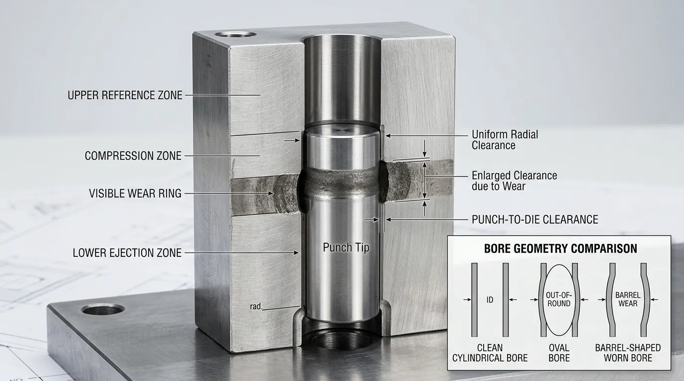
A tablet die bore can experience both dimensional wear and surface deterioration. Dimensional wear changes the bore profile or size. Surface deterioration includes scoring, Pitting, Corrosion, or roughness that may increase friction even when the diameter has not changed significantly.
A wear ring often develops around the working or compression zone. It may appear as a polished band, a change in reflection, or a visible transition on the internal surface. Its presence should trigger dimensional inspection, but it does not establish a pass or fail result.
Bore enlargement changes the functional clearance between the die and the punch tip. When that clearance becomes excessive or uneven, it can contribute to:
- powder leakage between the punch tip and die wall;
- thin fins or flashing around the tablet edge;
- accelerated punch-tip wear;
- poor tablet-edge definition;
- increased friction or inconsistent ejection;
- unstable performance across tools in the same set.
These symptoms are not proof of die wear. Formulation behavior, Lubrification, compression settings, tool alignment, Contamination, and punch condition can produce similar problems. They should be treated as inspection triggers.
Usure, Residue, Scoring, Effilage, or Geometric Distortion?
Several bore conditions can resemble wear or produce misleading measurements.
| État | Indication typique | Comment le confirmer |
|---|---|---|
| Résidus de produit ou film | Patchy deposit, sticky surface, unstable readings | Clean the bore using the approved procedure, then measure again |
| Bague d’usure | Bande localisée, polie ou agrandie | Measure at several depths above, within, and below the suspected area |
| Score en surface | Rayures ou rainures linéaires | Inspecter sous lumière dirigée et évaluer les dommages de surface séparément du diamètre |
| Réduction intentionnelle | Changement dimensionnel progressif le long du forage | Comparez les mesures avec le dessin d’outillage contrôlé |
| Ovalité | Lectures différentes selon les orientations | Mesurer à des positions angulaires ou axes de profil cohérents |
| Usure en forme de canon | Lecture plus importante au centre qu’aux positions supérieure et inférieure | Comparez les relevés sur plusieurs profondeurs définies |
| Erreur de jauge ou d’opérateur | Résultats incohérents à la même position | Recheck zero, contact position, Propreté, and measurement technique |
The tooling drawing is essential when a die includes intentional taper or a non-uniform profile. A designed dimensional transition must not be classified as service wear.
Outils et données de référence nécessaires avant la mesure
A practical tablet die-bore inspection setup normally includes:
- a suitable split-ball bore gauge or another qualified internal comparator;
- a mechanical or digital deviation indicator;
- the correct setting master or setting ring;
- the controlled tooling drawing and current revision;
- new-tool baseline readings, where available;
- directed lighting or a bore-inspection light;
- approved cleaning materials;
- an inspection record linked to the die or tooling-set ID;
- evidence that the instrument is within its calibration or verification period.
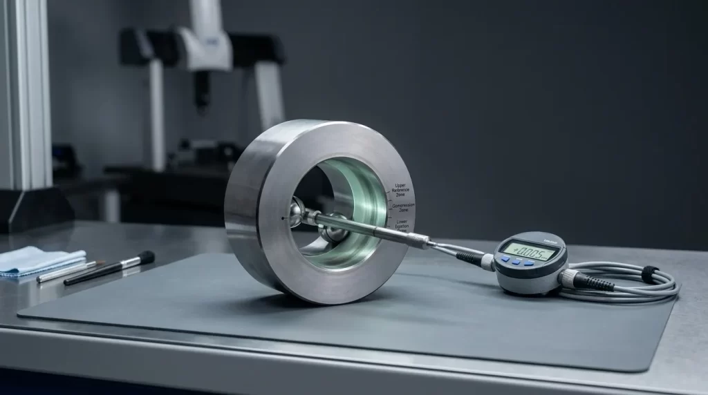
A split-ball bore gauge measures deviation relative to a reference rather than producing a complete geometric scan. The probe must match the bore range and profile being inspected. Original instrument documentation, such as the guidance for a Sonde à billes divisées et maître de réglage, should control the setup and handling method.
Calibration status alone does not prove that the measurement method is suitable for the decision. The instrument must also have enough resolution, Répétabilité, and measurement capability for the inspection limit being applied. Le Directives du NIST sur la traçabilité métrologique distinguishes traceability from fitness for a specific measurement purpose.
Jauge à bille divisée versus jauge à bouchon
| Méthode d’inspection | Utilisation principale | Limitation |
| Calibre à billes fendues | Mesure l’écart comparatif à des profondeurs et orientations sélectionnées | Requires correct zeroing, Alignement, contact selection, and operator technique |
| Jauge fixe de bougie | Confirme si une taille de jauge fixe peut pénétrer dans un alésage | Ne quantifie pas l’agrandissement localisé ni l’usure de la carte par la profondeur |
| Inspection optique ou coordonnée | Peut évaluer des profils complexes lorsqu’il est correctement configuré | May require specialist equipment, Fixation, software, and validated access to internal features |
A plug gauge can support a pass/fail check for a defined size, but it is not a complete substitute for localized wear measurement.
Dessin, Nominal Size, and New-Tool Baseline
Before measuring, confirmer:
- the correct die or tooling-set ID;
- the correct drawing revision;
- the nominal bore profile and units;
- whether the die has an intentional taper;
- the reference positions used for dimensional control;
- any measurements recorded when the die was new.
The nominal drawing dimension defines the intended design, while a new-tool baseline records the actual starting condition at controlled locations. Keeping both makes later wear trending more reliable.
Comment mesurer l’usure de la puce des comprimés
The approved site procedure and the gauge manufacturer’s instructions should take priority over a general guide. The sequence below shows the controls that a repeatable inspection process should contain.
Step 1 — Identify, Clean, and Visually Inspect the Die
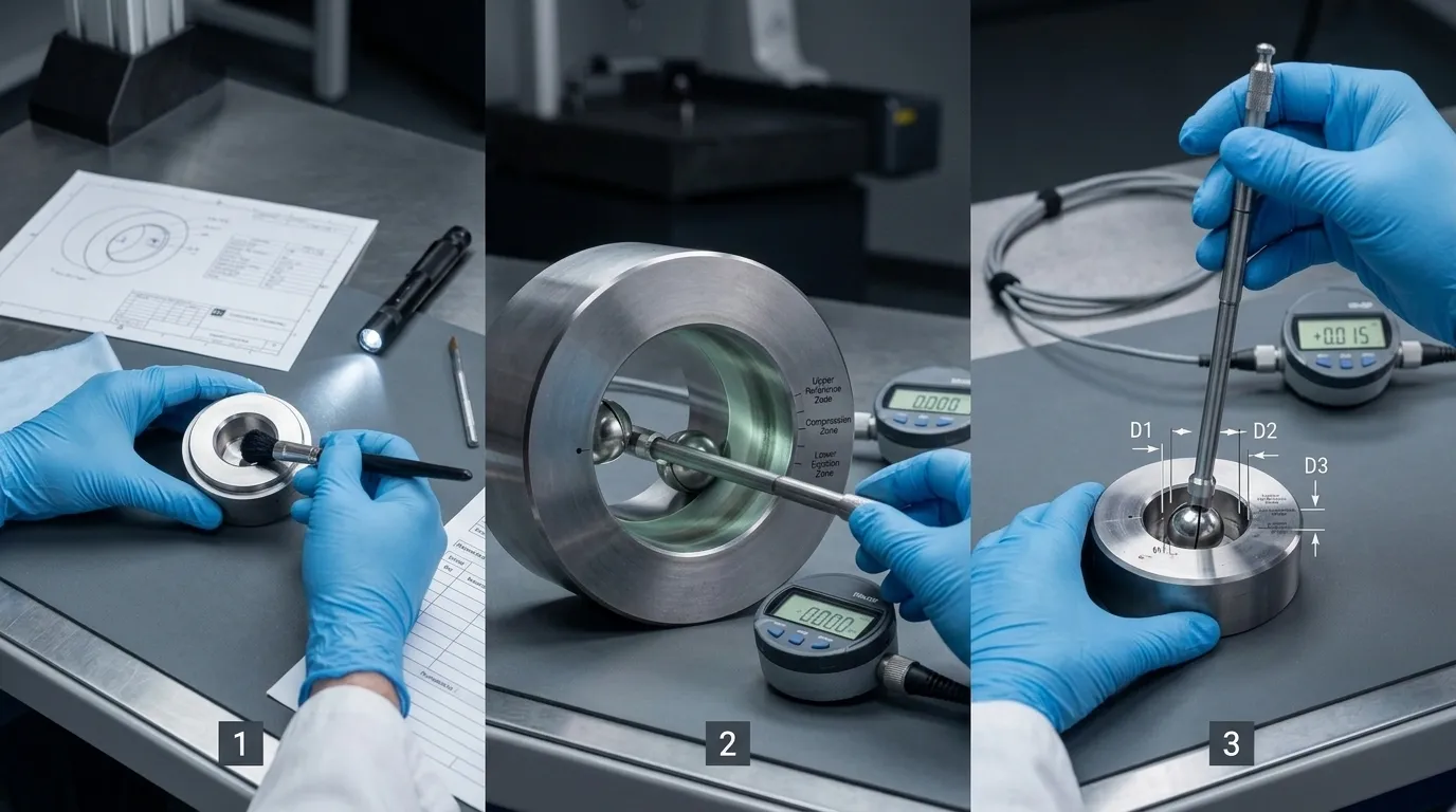
Record the die ID before cleaning or measuring. Confirm the drawing revision and previous inspection status.
Clean the bore thoroughly using the approved method. Product residue, polishing compound, lubrifiant, or corrosion products can alter the contact between the gauge and bore wall.
Inspect the full internal surface under directed light. Record visible conditions such as:
- a polished or enlarged wear ring;
- scoring or scratches;
- pitting or corrosion;
- fissures, Puces, or edge damage;
- residue that remains after cleaning;
- a visible taper transition;
- localized discoloration or roughness.
Photographs can help preserve evidence when unusual damage is found. Pour les opérations pharmaceutiques réglementées, written cleaning, Entretien, and inspection procedures should follow applicable requirements such as 21 CFR 211.67.
Étape 2 — Définir et vérifier la référence de jauge
Select the correct gauge range and contact configuration for the bore.
Clean and inspect the setting master. Place the probe in the master according to the instrument instructions, then align or rock it as required to locate the correct comparative point. Set the indicator to zero or to the documented reference value.
Record the gauge and indicator identification. After the complete measurement series, return to the setting master and verify that the reference has not shifted. A changed zero may indicate drift, Contamination, loose setup, or handling error.
Étape 3 — Mesurer une matrice ronde à des profondeurs et orientations définies
Do not rely on a single reading near the bore entrance. Localized wear may exist only in the compression or ejection region.
Define repeatable measurement positions from the tooling drawing and inspection procedure. A typical measurement map may include:
| Région de mesure | Objectif |
| Zone de référence supérieure | Établit l’état au-dessus de la zone principale de travail |
| Zone de compression ou de bague d’usure | Détecte l’agrandissement localisé là où le comprimé se forme |
| Zone inférieure ou zone d’éjection | Vérifie la région qui influence la libération de la tablette |
| Postes de transition supplémentaires | Confirms taper, barrel shape, or local damage |
At each depth:
- place the probe without dragging or forcing it against the bore;
- align it according to the approved technique;
- record the comparative reading;
- repeat the reading to check consistency;
- measure at additional orientations where required;
- record the maximum, Minimum, and repeated values.
Different readings by depth can indicate localized or barrel-shaped wear. Different readings at the same depth but different orientations may indicate ovality or directional damage.
The exact depths should come from the die geometry and inspection SOP. One universal set of depth values cannot suit every die design.
Étape 4 — Mesurer les coins oblongs et façonnés par profil
An oblong or shaped die cannot be represented by one diameter reading.
Use the drawing to identify:
- the major axis;
- the minor axis;
- critical radii or profile transitions;
- orientation references;
- measurement locations at each required depth.
Record every result with both its depth and profile orientation. Suitable contacts or a different inspection system may be needed for complex shapes. If the available gauge cannot contact the required surfaces consistently, do not force a result. Escalate the inspection to the tooling supplier or a qualified metrology process.
| Les profils | Approche de mesure minimale |
| Manche | Profondeurs multiples et orientations angulaires constantes |
| Ovale ou oblong | Major axis, minor axis, and repeated depths |
| Profil complexe | Drawing-defined contact points, Rayons, axes, and specialist method where required |
Step 5 — Repeat, Palmarès, and Confirm the Measurement Series
Repeat any unstable reading. If repeated values differ beyond the approved measurement-system capability, Vérifié:
- bore cleanliness;
- probe contact position;
- gauge alignment;
- indicator mounting;
- setting-master cleanliness;
- zero stability;
- contact wear or damage;
- operator technique.
The inspection record should contain more than a pass/fail result. Useful fields include:
- die or tooling-set ID;
- drawing number and revision;
- nominal profile;
- measurement depth;
- orientation or axis;
- repeated readings;
- maximum and minimum deviation;
- visual observations;
- instrument ID;
- setting-master ID;
- inspector and date;
- warning, rejection, or monitoring status;
- final disposition.
Recheck the setting master after the measurement series. If the reference has shifted, investigate and repeat affected readings.
Comment établir les limites d’inspection des cylindres de la puce sur tablette
There is no reliable universal wear limit for every tablet die.
A numerical example from another manufacturer, produit, or tooling set may be inappropriate because the acceptable bore condition depends on:
- punch-tip and die geometry;
- original tooling tolerances;
- tablet shape and edge requirements;
- formulation behavior and abrasiveness;
- powder leakage or flashing sensitivity;
- Performance d’éjection;
- press condition and alignment;
- measurement-system capability;
- validated process and product history.
Orientations de l’industrie sur Surveillance de l’usure des poinçons et matrices also treats acceptable deviation as product-dependent.
A new-tool manufacturing tolerance is not automatically the same as an in-service rejection limit. The first controls how the tool is produced. The second determines whether a used die still supports acceptable production.
Entrées pour les limites d’avertissement et de rejet
Use controlled evidence to establish two separate levels where appropriate:
- Warning limit: triggers investigation, shorter reinspection intervals, or increased process monitoring.
- Rejection limit: triggers quarantine, removal from service, ou remplacement.
The decision should consider:
| Entrée | Pourquoi cela compte |
| Dessin d’outillages | Defines the intended profile, Effilage, and original dimensional requirements |
| Base de base pour les nouveaux outils | Affiche les lectures réelles de départ à des positions contrôlées |
| Condition de pointe de pointe | Aide à évaluer la distance fonctionnelle entre les poinçons et les matrices |
| Qualité des bords et dimensions de la tablette | Montre si les outils produisent toujours des tablettes acceptables |
| Historique de solinage ou de fuite de poudre | Peut indiquer une augmentation de la dégagement fonctionnel |
| Tendance de la force d’éjection | May reveal friction, Préparation, rugosité, or wear requiring investigation |
| Historique de la formulation et de la série | Cela aide à expliquer les différences de taux d’usure |
| Reproductibilité et incertitude de la mesure | Détermine la confiance dans les lectures proches de la limite d’action |
| Recommandations de fournisseurs | Ajoute des conseils spécifiques à la conception lorsque l’outil exact est pris en charge |
| Validation du site et contrôle des modifications | Relie la limite à la performance approuvée du produit et du procédé |
The limit should be written into the inspection SOP with the reference data, measurement positions, required repetitions, responsibilities, and disposition rules.
Comment gérer les résultats limites
A reading close to the action limit should not receive an automatic pass or fail when measurement uncertainty could change the decision.
Use a controlled confirmation process:
- clean the bore and setting master again;
- verify the gauge zero;
- repeat the measurement;
- use a second qualified operator if required;
- compare the result with nearby depths and orientations;
- review recent tablet-quality and process data;
- confirm with a more capable measurement method when necessary;
- quarantine the die until the result is resolved;
- document the final decision.
Comment interpréter les résultats et choisir l’action suivante
| Constat de l’inspection | Action recommandée |
| Lecture instable ou contamination visible | Clean, verify zero, and remeasure |
| Résultat stable dans la limite autorisée et aucun dommage inacceptable | Retour au service et conservation du dossier |
| Résultat proche de la limite d’avertissement | Raccourcir l’intervalle de réinspection et examiner les tendances du processus |
| Résultat proche de la limite relative à l’incertitude de la mesure | Mettre en quarantaine et confirmer avec une méthode qualifiée |
| Limite de rejet dépassée | Retirez la puce du service |
| Severe scoring, craquelement, Ébréchage, or unsafe damage | Quarantaine quel que soit le résultat du diamètre |
| Exigence de dessin ou de profil incertaine | Demander un entretien du fournisseur ou de l’ingénierie |
| Usure répétée sur plusieurs outils | Review punch condition, Alignement, Matériel, Formulation, et conditions de fonctionnement |
Do not assume that dimensional enlargement is the only rejection reason. Surface damage can make a die unsuitable even when its measured diameter remains within the dimensional limit.
Traiter les symptômes qui devraient déclencher une inspection non programmée
An unscheduled die-bore inspection may be justified when production shows:
- rising or unstable ejection force;
- difficult tablet release;
- new flashing or powder leakage;
- unusual punch-tip scoring;
- binding or increased friction;
- a change in tablet-edge definition;
- recurring chipping, Plafond, or lamination;
- inconsistent performance among stations using the same tooling set.
Usé, Rough, scratched, or contaminated die surfaces can affect ejection friction, but ejection force also depends on formulation, Lubrification, Géométrie de tablette, et les conditions de compression. The relationship is explained in this technical overview of Force d’éjection en compression de comprimés.
These symptoms should trigger investigation, not an immediate conclusion that the die bore is worn.
Erreurs courantes de mesure de la puce des tablettes
| Erreur | Effet possible | Prévention |
| Mesurer un alésage contaminé | Faux agrandissement ou lectures instables | Nettoyez et inspectez visuellement d’abord |
| Utiliser la mauvaise portée ou contact de la sonde | Mauvais contact ou valeurs trompeuses | Ajustez la jauge au canon et au profil |
| Sauter la vérification du maître des paramètres | Référence incorrecte | Vérifiez avant et après la série |
| Mesurant à des profondeurs incohérentes | Les résultats ne peuvent pas être comparés dans le temps | Utilisez des positions définies par le dessin |
| Ignorer l’orientation | L’usure ovalable ou directionnelle peut être manquée | Axes d’enregistrement ou positions angulaires |
| Ne prenant qu’une seule lecture | L’erreur de l’opérateur peut passer inaperçue | Mesures répétées |
| Inclinaison ou balancement excessif | Valeurs maximales ou minimales artificielles | Suivez la technique de jauge qualifiée |
| Utiliser la mauvaise révision du dessin | La géométrie conçue peut être classée comme une usure | Confirmez le contrôle des documents avant l’inspection |
| Ignorer la réduction intentionnelle | La variation normale de conception peut sembler défectueuse | Comparez tous les résultats avec le dessin |
| En se fiant uniquement au statut d’étalonnage | La méthode peut manquer de résolution ou de répétabilité adéquate | Confirmer la capacité de mesure par rapport à la limite d’inspection |
| Enregistrement uniquement : réussite ou échec | Les tendances vestimentaires sont perdues | Conserver les valeurs brutes et les emplacements |
Fréquence d’inspection, Records, and Wear Trending
Measure new tooling before production use where practical. This creates a baseline for later comparisons.
Après ça, inspection frequency should reflect:
- tooling usage;
- Formulation de l’abrasivité;
- previous wear rate;
- product-quality risk;
- process symptoms;
- proximity to the warning limit;
- maintenance or cleaning events;
- the site’s validated procedure.
A fixed calendar interval may be insufficient. A die approaching its warning limit may require shorter intervals, while stable tooling with a documented history may follow the approved routine schedule.
Trend the actual readings by die ID, Profondeur, Orientation, and date. This allows the toolroom to see whether wear is stable, accelerating, or isolated to one region.
Die-bore measurement is only one part of a complete tooling inspection program. Punch dimensions require separate controls; voir Inspection de la longueur de travail de la perforatrice de tablettes for that adjacent procedure.
For applicable pharmaceutical operations, routine calibration, Inspection, checking, and records for mechanical or electronic equipment should follow written programs such as those described in 21 CFR 211.68.
Quand faire appel au fournisseur d’outillages
Supplier or specialist review is appropriate when:
- the original drawing is unavailable;
- the baseline condition was never recorded;
- intentional taper or profile geometry is unclear;
- a shaped bore cannot be measured reliably with the available equipment;
- borderline results remain unresolved;
- repeated wear suggests a wider tooling or process issue;
- a replacement die must match an existing tool set.
Provide enough information for a meaningful review:
- tooling and die identification;
- drawing and revision, if available;
- tablet and die profile;
- measurement depths and orientations;
- raw inspection readings;
- photographs of wear or damage;
- punch-tip condition;
- production symptoms;
- the required replacement or review objective.
Listes SunshinePro Outils personnalisés de presse à tablettes, including punches and dies, and states that custom processing can be based on drawings or samples. When measured wear has reached the approved rejection point or the original profile requires review, the practical next step is to submit the available drawing, Exemple, and inspection findings for a replacement-tooling discussion.
Partager:


Écrit par Sunshine
Au soleil, Nous sommes un fabricant et fournisseur professionnel de composants de moule de précision, proposant une large gamme de produits pour les applications de stampage et de moulage par injection. Notre objectif principal est le poinçage des coins, Goupilles et manchons d’éjection, et poteaux guides et bagues. Avec un usinage CNC avancé, Contrôle qualité strict, et de fortes capacités de production, Nous garantissons une fiabilité, Pièces de haute précision, ainsi que des composants standards en stock pour un approvisionnement mondial rapide et efficace.
ACTUALITÉS
OBTENIR UN SERVICE
Avec des pièces de qualité adaptées à tous les budgets et un personnel accueillant formé pour rendre votre visite informative et sans tracas.
