



Goupille de positionnement du moule vs Goupille guide: Comparaison des rôles d’alignement
A guide pin and a mold positioning pin both help align mold components, but they normally control different stages of that alignment.
A guide pin travels through a matching guide bushing to control how the mold halves approach, close, and separate. A positioning pin, locator, or interlock usually acts nearer the closed position, where it establishes more exact final registry or helps resist lateral displacement.
The two components are therefore not automatically interchangeable. A conventional mold may rely mainly on guide pins and bushings, while a mold with demanding shut-offs, offset loading, or strict parting-line alignment may use a guide system together with secondary positioning components.
Terminology varies between manufacturers. Some catalogs use “locating pin” as another name for a guide pin, while others use it for a separate final-positioning device. The component’s geometry, mating interface, engagement sequence, and mechanical role matter more than its name. Broader information about guide fits, bushing wear, and maintenance is covered in Broches et bagues de moulage (déduit).
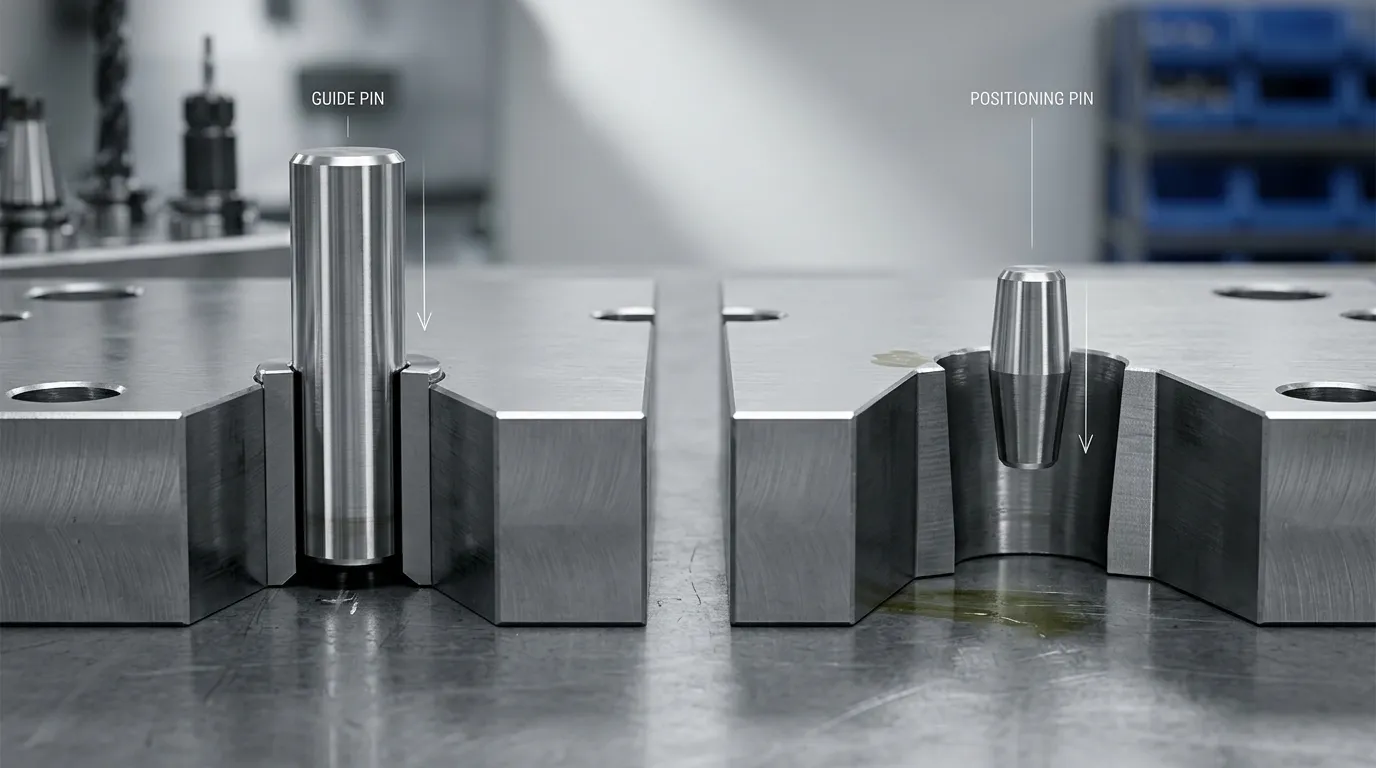
Guide Pin vs Positioning Pin: The Functional Difference
The clearest way to compare the two components is by the function they perform inside the mold.
| Point de comparaison | Épingle guide | Goupille de positionnement ou localisateur |
|---|---|---|
| Rôle principal | Guide le mouvement relatif entre les moitiés du moule | Établit ou affine la position fermée finale |
| Mouvement typique de fonctionnement | Glisse à travers une bague guide lors de l’ouverture et de la fermeture | Engages a receiver, locating bushing, socket, Effilage, or contact surface |
| Étage principal d’exploitation | Commence à agir lors de l’approche du demi-moule | Ça devient souvent le plus important vers la fermeture finale |
| Composante d’accouplement | Douille guide ou manchon guide | Locating bushing, receiver, socket, alignment lock, or mating locating surface |
| Principe d’adéquation | Nécessite suffisamment de jeu pour permettre des glissades répétées | May use closer, effilé, or positive contact depending on the design |
| Contribution à l’alignement | Contrôle de l’approche et guidage général de la moitié du moule | Contrôle la position finale du registre ou latérale |
| Rôle en charge latérale | May experience side loading, but should not automatically be treated as the sole lateral-positioning system | Peut être sélectionné spécifiquement pour aider à contrôler les mouvements latéraux près de la fermeture |
| Schéma d’usure courant | Scoring, Irritant, bushing wear, or increased clearance | Contact-face wear, Fretting, Épinglage, taper damage, or loss of final registry |
| Utilisation typique des systèmes | Partie fondamentale de nombreux systèmes de guidage de moule | Ajouté lorsque les exigences finales de positionnement dépassent ce que le système de guidage seul devrait fournir |
A guide pin is commonly called a leader pin, guide post, ou pilier guide. It enters a guide bushing and keeps the core and cavity halves moving along the intended path. For deeper coverage of guide geometry, Usure, et sélection, voir Goupilles guides de moule.
A positioning component works differently. Its purpose is not necessarily to guide the full mold stroke. It may engage only near closure, where the core half, cavity half, Inserts, shut-offs, and parting surfaces must reach a repeatable relationship.
Pourquoi les noms de catalogue peuvent être trompeurs
Component names are not fully standardized across mold-component catalogs.
“Guide pin” and “leader pin” are often used for the same sliding guide component. “Guide post” and “guide pillar” are also common regional or catalog terms.
“Locating pin” is less consistent. Depending on the supplier or drawing, it may refer to:
- Une goupille guide qui entre dans une bague
- Une goupille statique utilisée pour localiser les plaques assemblées
- Un composant effilé ou droit utilisé pour le positionnement final
- Une goupille qui engage un boîtier séparé ou une bague de localisation
- Partie d’un système plus large de verrouillage d’alignement ou d’interverrouillage
A static dowel pin should not be confused with a component that operates throughout mold opening and closing. A dowel may establish the assembled position of two plates, while a guide pin moves repeatedly through a bushing during each cycle.
To identify the component correctly, examine:
- Que ce soit un passage à travers une bague
- Quand il s’engage lors de la fermeture du moule
- Que cela fonctionne sur toute la course
- Que son objectif principal soit le guidage de mouvement ou la position finale
- Whether it has straight clearance, tapered contact, or positive locating surfaces
- Ce qui charge le dessin s’attend à ce qu’il résiste
Comment les composants de guidage et de positionnement s’engagent lors de la fermeture du moule
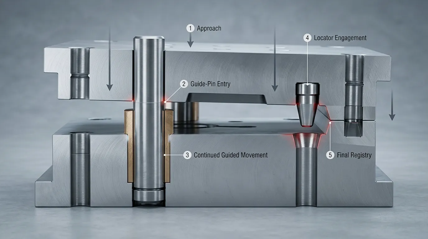
A combined guide and positioning system can be understood as a sequence rather than two components performing the same task.
- The mold halves begin to approach.
The lead-in portion of the guide pin moves toward the guide bushing. - The guide pin enters the bushing.
The pin-and-bushing relationship controls the relative movement of the core and cavity halves. The sliding interface helps prevent uncontrolled lateral movement during approach. - The mold approaches the closed position.
The guide system continues to control movement, but its operating clearance still allows repeated sliding. - The secondary positioning element engages.
Where the design includes a positioning pin, tapered locator, alignment lock, or mold interlock, that component begins controlling the final positional relationship. - Final registry is established.
The parting surfaces, shut-offs, Cavités, Couleurs, and related mold features reach their intended closed relationship before or during clamping.
During opening, this sequence reverses. The final-positioning surfaces disengage, and the guide pins continue controlling separation through the guide bushings.
This sequence is a functional example, not a universal timing rule. Actual engagement depends on the component geometry and mold drawing. In some designs, components described as “locating pins” may begin engaging earlier than expected because they also perform a guiding function.
Can a Positioning Pin Replace a Guide Pin?
Usually, a final-positioning component should not be assumed to replace the full-stroke guidance provided by guide pins and bushings. It may not have the length, sliding interface, or engagement range needed to control the mold throughout opening and closing.
The reverse is also true. A guide pin should not automatically be expected to provide every final-positioning function. Its sliding clearance, wear condition, span, and exposure to lateral forces may limit how accurately it controls the final relationship between critical mold features.
La bonne disposition dépend de l’application.
| État de la moisissure | Approche d’alignement probable |
| Moule conventionnel avec des exigences d’alignement modérées et une charge latérale limitée | Des goupilles guides et des bagues peuvent être suffisantes |
| Moule avec une géométrie de séparation irrégulière ou des fermetures exigeantes | Un système de guidage plus un positionnement secondaire peut être approprié |
| Moitiés de moule grandes ou lourdes | Un support supplémentaire de localisation ou d’interverrouillage peut être nécessaire |
| Offset cores, asymmetric forces, ou chargement latéral | Les composants de positionnement final peuvent aider à contrôler le registre latéral |
| Alignement final critique entre les caractéristiques du moule | Le système de guidage et les composants de positionnement dédiés peuvent fonctionner ensemble |
| Problèmes existants de blocage ou de mouvement | Inspect guide pins, Silents, mounting alignment, Contamination, et l’usure |
| Décalage existant de la ligne de séparation malgré un mouvement de guide acceptable | Inspectez les surfaces de positionnement final et de localisation ainsi que le système de guidage |
Quand les goupilles guides peuvent être suffisantes
Guide pins and bushings may provide enough alignment when:
- Le moule possède une géométrie de séparation conventionnelle
- Les forces latérales et asymétriques sont limitées
- Les exigences d’alignement sont modérées
- La portée guide et la disposition des composants sont adaptées
- Les goupilles et les bagues restent correctement montées et dans une usure acceptable
- Il n’existe aucune preuve récurrente de perte au registre final
- Le système de guidage a été choisi en fonction de la taille réelle du moule et des conditions de fonctionnement
This does not mean that guide pins are imprecise. It means that their main job is controlled movement through a sliding interface. The required running clearance and accumulated wear must be considered when deciding whether they can also satisfy the mold’s final-positioning requirements.
Lorsque le positionnement secondaire est plus approprié
A separate positioning system becomes more relevant when the mold has:
- Caries profondes ou relations fermées exigeantes
- Moitiés de moule en mouvement grand ou lourd
- Irregular, Égrégé, or non-flat parting surfaces
- Charges décalées ou arrangements asymétriques de cavités
- Actions secondaires qui créent des forces latérales significatives
- Critical insert, Noyau, or cavity registry requirements
- Décalage répété de lignes de séparation qui n’est pas seulement causé par des bagues guides usées
- Températures de fonctionnement qui affectent de manière significative les relations de dégagement ou de contact
Secondary positioning does not have to mean one specific pin design. The function may be performed by a straight locator, tapered locator, alignment lock, side lock, or mold interlock.
Straight and tapered positioning geometries create different engagement and contact conditions. That choice should be evaluated separately rather than treated as part of the basic guide-pin comparison.
Quand les deux systèmes doivent fonctionner ensemble
Many demanding molds separate the two alignment functions:
- Guide pins and bushings control approach, closing movement, and opening movement.
- Positioning pins, locators, or interlocks refine the final closed position.
This division allows each interface to perform the task it was designed for. The guide components do not have to act as rigid final locks, while the positioning components do not have to guide the mold through its full travel.
The systems still have to be coordinated. If the guide arrangement permits the mold halves to reach a position that conflicts with the locator geometry, the positioning components may strike, bind, or wear unevenly. Mounting accuracy, engagement order, Conditions thermiques, and the relationship between male and female components must therefore be considered together.
How Fit, Side Load, and Temperature Change the Selection
Fit is one of the main reasons a guide pin and positioning component cannot be evaluated in the same way.
A guide pin must move repeatedly through its bushing. The interface needs operating clearance that accounts for component tolerances, Lubrification, Contamination, Température, mounting alignment, et l’usure. Too little functional clearance can cause binding or galling. Too much clearance can reduce alignment repeatability.
A positioning component may use a different contact principle. A tapered locator or interlock can approach a more positive final relationship as the mold closes. A straight positioning pin may use a controlled fit with a matching receiver. The correct choice depends on how much movement must be allowed before engagement and what load the interface must carry.
Side load also changes the decision. If lateral force acts on the mold halves, guide pins may be pushed against one side of their bushings. Repeated loading can produce uneven wear, increased clearance, ou reliure. A dedicated positioning system can be used to control the final lateral relationship rather than leaving that entire function to the guide components.
Temperature must be included in the evaluation. Plaques de moulage, Quilles, Silents, and locating components expand as temperature changes. That expansion can alter sliding clearance or increase contact at locating surfaces. A fit that works during room-temperature assembly may behave differently under operating conditions.
Standardized limits-and-fits terminology, such as the system defined in ISO 286-1, can reduce drawing ambiguity. It does not establish one universal guide-pin or positioning-pin fit. The designer still has to select the tolerance relationship for the actual material, Température, Lubrification, Charge, Géométrie, and component function.
Wear and Failure Clues: Which Alignment Function Is Being Lost?
The wear pattern often indicates whether the problem is mainly related to movement guidance or final positioning.
| Condition observée | Zone plus probable à inspecter | Pourquoi |
| Binding lors de l’ouverture ou de la fermeture | Goupilles guides, Silents guides, mounting alignment, Contamination | Le chemin du guide glissant peut être restreint ou mal aligné |
| Longues marques de pointage sur une quille | Interface guide | Contact coulissant, Contamination, Lubrifiant insuffisant, or side loading may be present |
| Gallage ou transfert de matériau | Goupille guide et paire de bagues | L’usure adhésive peut se développer lorsque des surfaces glissantes entrent en contact dans des conditions inadaptées |
| Usure inégale des bagues | Système de guidage et alignement du moule | Une erreur de charge latérale ou de montage peut forcer le contact d’un côté |
| Augmentation de la liberté de circulation avant la fermeture | Espace de dégagement des guides | L’usure a peut-être élargi la relation entre goupilles et bagues |
| Fretage ou patchs de contact polis sur les surfaces de localisation | Système de positionnement | Le contact répété ou le micro-mouvement affecte les surfaces de position finale |
| Arêtes ou bords endommagés sur un localisateur | Séquence d’engagement ou désalignement | Les composants peuvent frapper avant d’être correctement alignés |
| Cône endommagé ou contact effilé inégal | Composante de positionnement | Le contact final de localisation peut ne plus être correctement distribué |
| Décalage de lignes de départ ou incohérence de coupure | Système d’alignement complet | Loss of final registry may involve locators, Tenue de guide, Mouvement des plaques, or other mold conditions |
No single symptom proves that one component has failed. Flash, Désaccord, or binding can have several causes. Inspection should include both male and female components, their mounting features, the mold plates, état de lubrification, Contamination, and evidence of lateral loading.
Replacing only a worn pin may not restore the original relationship if the mating bushing or receiver is also damaged. The complete interface should be evaluated.
Liste de contrôle de sélection pour les plans et les demandes de soumission des fournisseurs
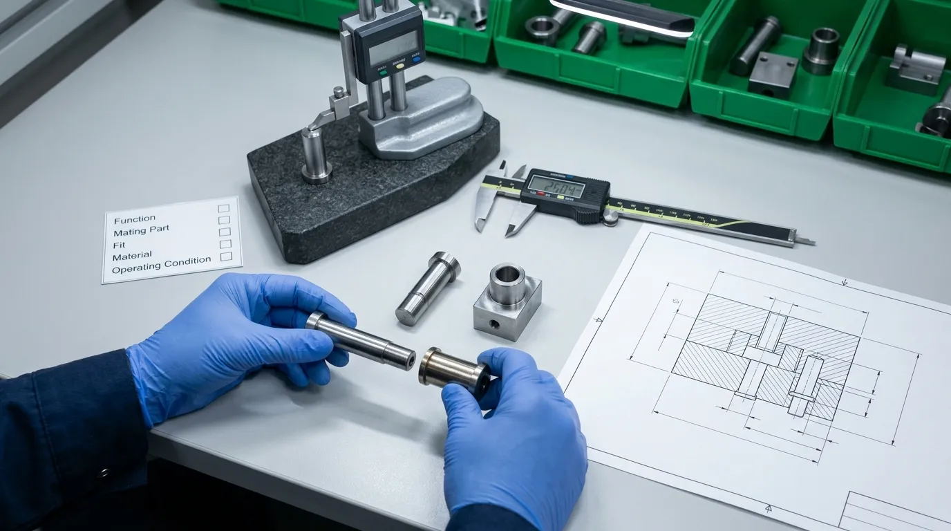
A supplier cannot reliably determine the correct component from the words “guide pin” or “positioning pin” alone. The RFQ should define the required function and the mating relationship.
Include the following information:
- Required function: State whether the component provides full-stroke guidance, final registry, lateral positioning, static plate location, or a combined role.
- Assembly drawing: Provide a mold section showing where the pin, Silent, receiver, or locating surface is installed.
- Mating components: Identify both sides of the interface rather than specifying only the pin.
- Dimensions nominales: Include diameters, Durées, Épaules, Effilés, engagement depths, and mounting dimensions.
- Tolérances dimensionnelles: Identify the tolerance for each critical feature and make clear which diameter or surface it applies to.
- Geometric tolerances: Add straightness, Concentricité, Perpendiculité, or position controls where the design requires them.
- Material and heat treatment: Specify these only according to the approved design or service conditions.
- Hardness and surface finish: State the required features instead of assuming one universal value for all guide or positioning parts.
- Revêtement ou traitement de surface: Include it only when required and define the treated surfaces.
- Operating temperature: Describe the expected thermal condition where it may affect clearance or locating contact.
- Lubrication and contamination conditions: Indicate whether the component operates with lubrication and whether dust, resin residue, or other contamination is expected.
- Direction de la charge: Identify unusual lateral, offset, or asymmetric loading.
- Installation method: Define press-fit, Conservé, épaule, bridé, or other mounting requirements.
- Replacement access: Show how the component will be removed and whether the mating part is replaceable.
- Inspection requirements: Request dimensional reports or other records where critical features require verification.
The sourcing route also matters. A catalog component may be appropriate when the required geometry, Ajusté, Matériel, and mounting method match an established standard. A drawing-based component may be needed when the mold has unusual engagement geometry, nonstandard dimensions, special mating surfaces, or application-specific material requirements.
SunshinePro publishes guide posts, Silents, locating-related accessories, et autres Moulage des pièces standard. The company also states that custom mold and die accessories can be produced from drawings or samples. Those broad capabilities do not replace the need for a complete technical specification.
Choisir le bon système d’alignement pour le moule
There is no universal winner in the mold positioning pin vs guide pin comparison.
Use guide pins and bushings when the mold needs controlled relative movement during opening and closing. Use a positioning component when the design requires more definite final registry, better control of lateral displacement, or repeatable contact near the closed position. Use both when movement guidance and final positioning are separate requirements.
The final decision should come from the mold drawing, parting geometry, expected loads, Température de fonctionnement, allowable clearance, mating-component design, and maintenance access—not the catalog name alone.
For a standard-part or drawing-based component review, prepare the mold section, required function, mating geometry, Dimensions, Tolérances, Besoins matériels, and operating conditions before contacter SunshinePro.
Partager:


Écrit par Sunshine
Au soleil, Nous sommes un fabricant et fournisseur professionnel de composants de moule de précision, proposant une large gamme de produits pour les applications de stampage et de moulage par injection. Notre objectif principal est le poinçage des coins, Goupilles et manchons d’éjection, et poteaux guides et bagues. Avec un usinage CNC avancé, Contrôle qualité strict, et de fortes capacités de production, Nous garantissons une fiabilité, Pièces de haute précision, ainsi que des composants standards en stock pour un approvisionnement mondial rapide et efficace.
ACTUALITÉS
OBTENIR UN SERVICE
Avec des pièces de qualité adaptées à tous les budgets et un personnel accueillant formé pour rendre votre visite informative et sans tracas.
