



Conception de goupille perforatrice pour motifs répétés de petits trous
Perforation punch pin design is not simply a matter of choosing a small diameter and a hard material. A reliable design must coordinate the hole pattern, sheet material, Géométrie du poinçon, support system, combined cutting force, L’Autorisation, slug path, and maintenance method.
The challenge becomes greater as hole diameter decreases or more holes are punched during each stroke. Un long, unsupported tip may deflect. A dense cluster can exceed press capacity or distort the sheet. Small slugs may clog the die or return to the work surface. The punch therefore has to be designed as part of the complete cutting system.
Pour des informations plus larges sur les poinçons, stripper systems, Éléments guides, and other tooling parts, voir le Guide des composants de la puce (déduit). This guide focuses specifically on punch pins used for repeated small-hole patterns.
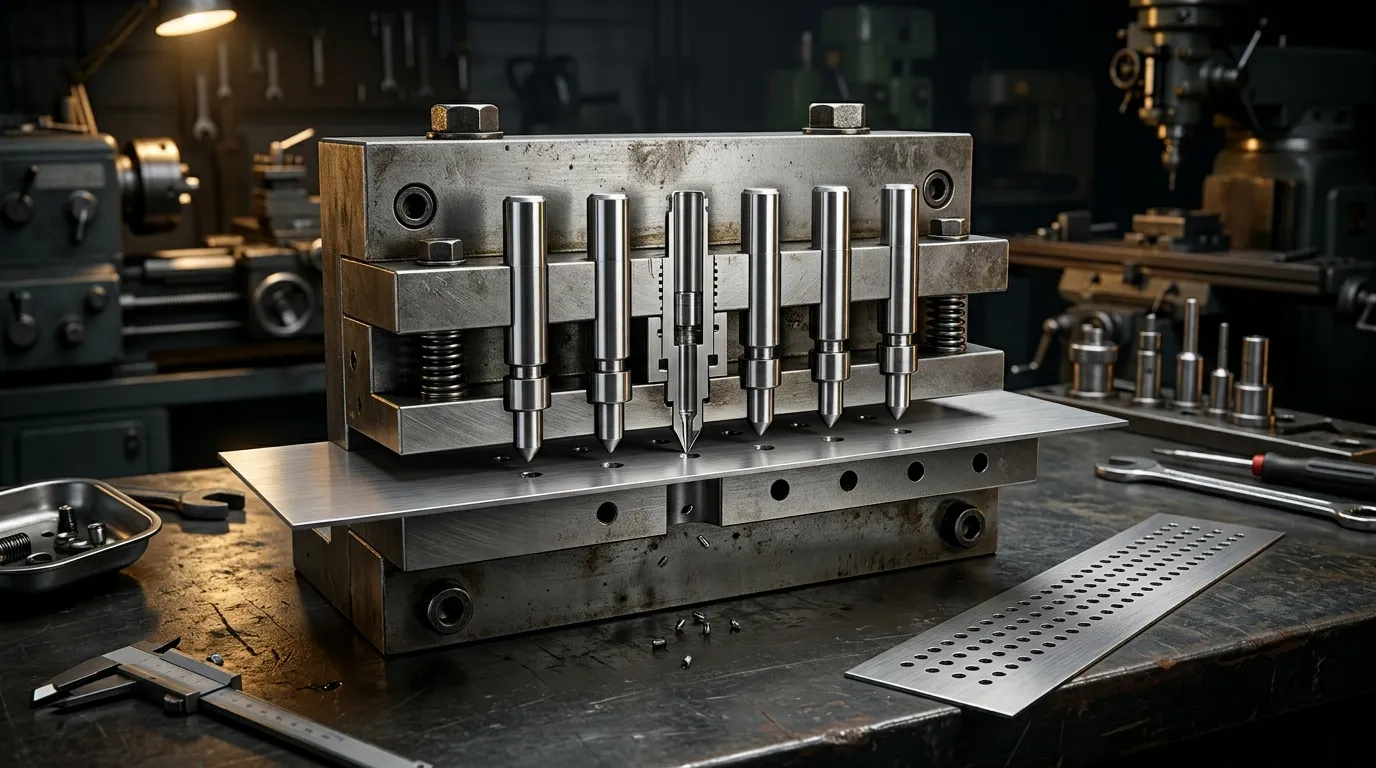
What Must Be Designed Together in a Perforation Punching System?
A perforation punch pin forms one part of a load path that extends through the tool:
- The cutting tip enters the sheet.
- The punch shank transfers the cutting load upward.
- The punch plate locates and retains the pin.
- The backing plate supports the punch against axial reaction.
- The stripper controls the sheet and may guide the punch near its tip.
- The die opening provides the opposing cutting edge.
- The slug passes through the die relief and exits the tool.
A weakness in any one part can affect the entire operation. A strong punch material will not prevent failure if the working tip is too long, the stripper allows lateral movement, or the die opening is misaligned. A correctly sized pin can still produce unstable results if several tips create excessive combined force or if the slug path becomes blocked.
This is why perforation tooling should not be treated as an isolated component-selection exercise. General die construction and die-type decisions are covered more broadly in the Guide des matrices de poinçon. Tiens, the design starts with the repeated hole pattern and works inward toward the punch pin.
Définissez le motif de trous et les exigences de la feuille avant de concevoir la goupille
The working diameter is only one input. Before selecting a pin architecture or material, define the conditions that control the cutting operation.
The design package should include:
- Matériau et état de la feuille
- Épaisseur nominale de la feuille et tolérance à l’épaisseur
- Hole diameter, Forme, and dimensional tolerance
- Inclinaison du trou dans chaque direction
- Matière restante entre les trous adjacents
- Pattern arrangement, including aligned or staggered rows
- Espace ouvert obligatoire
- Direction de meule et hauteur autorisée
- Exigences de planéité de la feuille
- Volume de production attendu
- Capacité de presse et de station disponible
- Exigences en matière de lubrification et de propreté
- Méthode de nettoyage et de remplacement planifiés
These inputs are connected. Changing the sheet thickness affects cutting force, slug geometry, practical hole size, and die clearance. Reducing hole pitch leaves less material between adjacent openings and may weaken both the sheet and the die. Increasing the number of tips raises the combined cut perimeter and total force.
Hole Size, Matériel, and Thickness Set the First Feasibility Check
A small hole is more difficult to punch when its diameter approaches or falls below the sheet thickness. The exact practical limit depends on the work material, punch material, Orientation, Alignement, tool construction, and required hole quality.
A hard or high-strength sheet generally creates greater cutting load than a softer material of the same thickness. A small punch cross-section must carry that load without bending, Ébréchage, or breaking. Guided tooling may support a more demanding diameter-to-thickness relationship than a long, non-guided punch, but guidance does not eliminate the need for sufficient punch strength.
Références techniques telles que les directives de MISUMI sur Perforation de trous de petit diamètre emphasize short working sections, stepped support, and controlled slug removal. Supplier ratios can be useful for an early feasibility check, but they should not be treated as universal design limits.
Pitch, Remaining Web, and Flatness Define the Pattern-Level Risk
Hole pitch is the centre-to-centre distance between adjacent perforations. The remaining web, sometimes called the bridge, is the material left between their edges.
A pattern may contain individually feasible holes but still be difficult to manufacture if the web becomes too narrow. Dense perforations can:
- Réduire la rigidité locale des feuilles
- Affaiblir le matériau de la matrice entre les ouvertures
- Augmenter le risque d’interaction entre trous
- Étirement ou ondulation de la feuille de produits
- Créez un encapsulage à l’huile sur un panneau plus grand
- Concentrez la charge de coupe dans une région de l’outil
Aligned rows and staggered rows do not distribute load in the same way. A staggered pattern may improve open-area distribution or reduce direct alignment of weak sections, but it does not automatically solve distortion. The finished panel’s flatness requirement must be considered with the complete punching sequence.
Choisissez l’architecture de goupille perforatrice qui supporte la petite pointe de travail
A perforation pin normally contains several functional regions:
- La pointe de travail qui crée le trou
- Une transition ou épaule derrière la pointe
- Une tige plus grande qui transfère et supporte la charge
- Une fonction de rétention qui localise la perforatrice dans la plaque perforatrice
- Une marge de réglage ou de rectification si nécessaire
The small working portion should be only as long as the operation needs. Extra unsupported length increases sensitivity to lateral movement and bending. The required length must still allow suitable penetration, stripper guidance, withdrawal, and future sharpening.
Straight, Stepped, and Multi-Step Pins Serve Different Section Sizes
| Architecture des broches | Logique de conception typique | Principal avantage | Principale limitation |
|---|---|---|---|
| Épingle droite | La section de travail et la tige ont la même section transversale ou une section similaire | Géométrie simple et fabrication | Une section toute petite de longueur complète peut manquer de rigidité |
| Épingle à marche | La petite pointe de travail est soutenue par une tige plus grande | Meilleur support derrière la section de coupe | La position et la transition des épaules nécessitent une conception soignée |
| Broche à plusieurs étapes | Plusieurs transitions relient une petite pointe à un corps beaucoup plus grand | Un changement plus progressif entre des sections très différentes | Géométrie et inspection plus complexes |
La discussion de MISUMI sur Conception de la poinçonne perforatrice distinguishes straight, Égrégé, and multi-step punches according to the strength and size of the functional section.
A stepped punch is often considered when the required hole is too small for a long straight pin to remain sufficiently rigid. The larger shank provides support, while the smaller section performs the cut. The transition should transfer load without creating an unnecessarily sharp stress concentration.
Longueur de travail et géométrie de transition Contrôle la déflexion et la contrainte
Two punches with the same tip diameter can behave very differently if one has a much longer unsupported working section.
As the slender section becomes longer, the pin becomes more vulnerable to:
- Déviation latérale
- Désalignement avec l’ouverture du dé
- Usure latérale inégale
- Ébréchage du tranchant
- Casse par fatigue
- Flexion lors du démontage
The transition behind the working tip also matters. An abrupt reduction in section can create a highly stressed area. A better-supported transition distributes the load into the larger shank while preserving the required access to the sheet and stripper.
There is no single universal working-length ratio for every material and application. The final geometry must account for penetration, Épaisseur de la feuille, stripper position, guidance length, regrinding allowance, and the actual load on the tip.
Guide, Retain, and Back the Punch Through the Full Stroke
Small punches require both axial and lateral support.
The punch plate retains and locates the shank. The backing plate supports the punch against cutting reaction. The stripper controls the sheet during withdrawal and may guide the punch close to the cutting region. These elements must remain aligned with the die opening.
Even a correctly dimensioned pin can fail if the support system allows side loading.
Le guidage du décapant limite le passage du poinçon près de la pointe de coupe
A stripper-guided punch passes through a controlled opening in the stripper plate before entering the sheet. This close support reduces the distance over which the small tip can move laterally.
Note technique de MISUMI sur Guidage pour décapants pour poinçons à évasement de trous explains that small punches are especially vulnerable to lateral movement. The stripper can reduce that movement, but only when the stripper itself moves accurately.
If the stripper tilts, shifts, or has excessive clearance, it may transfer error to the punch rather than correcting it. The stripper opening, punch shank, and die opening must therefore be treated as one alignment system.
La plaque perforatrice et la plaque de support complètent le trajet axial de charge
The punch plate positions the pin, but it may not provide sufficient resistance to concentrated axial load by itself. A small punch head or shank can create high local pressure behind the pin.
A backing plate spreads this reaction into a stronger supporting area. Without adequate backing, the punch may indent or sink into the holder, changing its working height and alignment.
Les directives de MISUMI sur Conception de la plaque arrière highlights this issue for punches with small supporting cross-sections.
The load path should remain flat, rigid, and correctly located. A hard punch placed against a weak or poorly supported holder can still lose position under repeated loading.
Ajustez le nombre de goupilles et la disposition du motif à la force de poinçon disponible
A cluster punch produces several holes in one stroke. This can reduce the number of press cycles required, but the press must cut the combined perimeter of all engaged tips.
The total load is not determined by hole count alone. It depends on:
- Périmètre total engagé de coupe
- Épaisseur de la feuille
- Résistance au cisaillement du matériau de travail
- Nombre de pointes coupant simultanément
- Netteté du poing
- Le dégagement
- Conditions de démontage
- Efficacité des outils et de la presse
Adding more tips may increase output per stroke, but it also raises cutting load, slug volume, maintenance exposure, and the possibility of sheet distortion.
Estimate Force from Total Cut Perimeter, Not Hole Count Alone
A conceptual punching-force relationship is:
Force de poinçon ≈ périmètre total de coupe × épaisseur de la feuille × résistance au cisaillement du matériau
For a cluster, the total cut perimeter is the sum of the perimeters of all tips engaged during the same part of the stroke.
This means ten small round holes do not create the same load as ten slots with a much greater combined perimeter. Two patterns with similar open area may also require different force because their edge lengths differ.
Mate Precision Guidage par le punching de cluster uses total cutting perimeter as a central force-planning factor and recommends checking cluster load against the machine and station limits.
The calculation should be treated as an engineering estimate. The actual tool must also account for stripping force, load balance, État de presse, and the manufacturer’s tooling limits.
Le décalage et la répartition de la charge peuvent réduire les problèmes au niveau du motif
If every adjacent tip enters the material at the same time, cutting load may be concentrated within a small area. This can increase peak force and stretch the sheet around the pattern.
Possible design responses include:
- Répartition du schéma sur plusieurs stations
- Utiliser moins de pointes actives
- Organiser les lignes pour que l’engagement soit réparti
- Écalyser les longueurs des pointes là où le système d’outillages le permet
- Équilibrer le motif autour du centre d’outils
- Modification de la séquence de poinçage
These methods can reduce local concentration, but they may also add tool complexity or change the loading sequence. They must preserve the finished hole locations and part geometry.
Informations de Wilson Tool sur Perforation avec des outils à grappe also identifies sheet stretch and oil-canning as practical concerns in dense perforation work.
Coordonner le dégagement des coins avec l’évacuation des projectiles
The punch and die opening form one cutting pair. Clearance between them influences cutting load, fracture behaviour, Formation de la meule, Usure des outils, and slug release.
Repeated small-hole patterns make waste handling especially important. A cluster with 20 tips creates 20 slugs during each complete punching cycle. Even when each slug is small, the cumulative waste flow can become substantial.
The die must provide:
- Jeu de coupe approprié
- Adéquat pour le pays
- Relief sous le tranchant
- Un itinéraire de sortie continu
- Accès pour inspection et nettoyage
- Protection contre la recirculation des slugs
Clearance Must Be Verified for the Material, Épaisseur, and Required Edge
Clearance is normally considered per side between the punch and die cutting edges. The appropriate value depends on the sheet material, Épaisseur, condition d’arête requise, punch condition, and tooling method.
Clearance that is too small may increase force and wear. Clearance that is too large may increase burrs, edge rollover, ou variation dimensionnelle. As the punch and die wear, effective clearance changes even if the original dimensions remain correct.
For this article, the important point is that the pin diameter cannot be finalized independently from the die opening. Exact clearance values require material- and application-specific calculation and validation.
Chaque trou supplémentaire ajoute un autre slug qui doit sortir de manière fiable
Small slugs can:
- Accumulation dans des passages de coin restreints
- Pont sur des sections étroites en relief
- Compacter en bouchon
- Collez à la face du poing
- Retour à la surface de travail
- Endommager la feuille lors d’un coup ultérieur
The die relief should allow slugs to move away without trapping one another. Tool access should permit cleaning before debris raises the cutting load or damages the punch.
Slug pulling requires particular attention. A slug that follows the punch upward may be pressed back into the sheet or trapped between the tool and workpiece. Geometry, Dégagement, Lubrification, Condition de la surface, and waste-path design can all influence this behaviour.
Sélectionnez le matériau de la goupille et le traitement de surface selon le mode de défaillance attendu
The hardest available punch material is not automatically the best choice. Material selection should respond to the dominant failure risk.
Common risks include:
- Usure abrasive
- Usure de l’adhésif ou galure
- Ébréchage des bords
- Casse par fatigue
- Déformation plastique
- Impact du désalignement
- Corrosion ou dommages de surface
A material that resists wear well may be less tolerant of shock or side loading. A tougher material may survive misalignment better but require more frequent sharpening.
Acier à outillage, HSS, and Carbide Balance Wear and Toughness Differently
| Famille matérielle | Caractéristiques utiles | Principal problème de conception |
| Acier à outillage | Broad balance of toughness, Résistance à l’usure, Traitement thermique, and regrindability | La performance dépend fortement du grade et du traitement thermique |
| Acier à grande vitesse ou métallurgie à poudre | Peut offrir une meilleure résistance à l’usure tout en conservant une robustesse utile | Le coût et la difficulté de l’usinage peuvent augmenter |
| Carbe | Forte résistance à l’usure et résistance à la compression | Plus sensible aux impacts, Ébréchage, and alignment errors |
Carbide may be suitable for stable, abrasif, high-volume applications, but it is not a universal solution for every small hole. A slender carbide tip exposed to side load or impact may chip where a tougher steel punch would survive.
The selection should consider the sheet material, working-tip diameter, longueur non supportée, Orientation, Lubrification, État de presse, and previous failure history.
SunshinePro Goupille de perforation personnalisée Liste de pages SKH51, SKH9, DC53, ASP-grade materials, and carbide among its stated material options. Final suitability still has to be confirmed against the actual drawing and application.
Finition de surface, Revêtement, and Lubrication Address Surface Interaction
Surface finish influences friction, Micro matériel, Sortie, and the condition of the substrate beneath a coating. A smoother working surface may help reduce adhesion in suitable applications, but finish alone cannot correct an unsupported tip or misaligned die.
Coatings such as TiN, TiCN, and DLC may be considered for selected wear or friction conditions. Their value depends on:
- Substrat à poinçon
- Matériau de la pièce à travailler
- Préparation de surface
- Géométrie des arêtes
- Lubrification
- Température
- Impact et chargement latéral
- Adhérence du revêtement
A coating should not be used as a structural repair. It cannot compensate for excessive working length, poor stripper guidance, weak backing, or incorrect clearance.
Lubrication is also part of the system. It can reduce friction, Usure par adhésif, and stripping resistance, but the lubricant must be compatible with the work material, downstream process, and cleanliness requirements.
Design the Tool for Replacement, Affûtage, and Inspection
Perforation tooling should be serviceable before the first production run begins. A design that performs well initially but cannot be repaired economically may create unnecessary downtime later.
The maintenance plan should address:
- Remplacement individuel de la broche
- Disponibilité des pointes de secours
- Marge d’aiguisage
- Ajustement de la longueur après le remuelage
- Accès aux broches conservées
- Identification des pointes
- Points d’inspection
- Limites de remplacement
Les outils fixes à pointes multiples et les embouts remplaçables créent différents modèles d’entretien
A fixed multi-tip punch may be compact and mechanically simple. If one tip is damaged, cependant, the repair may affect the complete tool.
Replaceable-tip systems allow individual punches to be changed without discarding the whole cluster body. Wilson Tool describes replaceable configurations among its perforation-tool options.
Replaceable tips are not suitable for every pattern. Very close spacing may leave insufficient room for individual retention features. The design must also provide access for removal, accurate location after replacement, and a practical spare-parts system.
The best configuration depends on pattern density, Fréquence de maintenance, tool size, and the cost of replacing one damaged position compared with servicing the complete assembly.
Le rectification change plus que le tranchant
Sharpening removes material from the cutting face. This changes the punch length and may alter penetration, Ajustement, stripper relationship, or the available guided length.
Après le remplumage, Inspecter:
- Diamètre ou profil de la pointe
- Condition de pointe
- Longueur de travail restante
- Droiture
- Concentricité entre la pointe et la tige
- Condition de transition
- Dégâts de surface
- Fonctionnalité de rétention
- Longueur totale ou position d’ajustement
A pin should not remain in service merely because its edge can still be sharpened. If the remaining geometry no longer provides sufficient support or alignment, replacement may be safer than another regrind.
Diagnostiquer les problèmes de motifs en examinant la variable de conception qui les sous-tend
Production symptoms rarely identify one guaranteed root cause. They do indicate which design relationships should be checked first.
| Production symptom | Causes possibles de conception | Points à examiner |
| Errance du poinçon ou variation de la position du trou | Long unsupported tip, weak stripper guidance, Désalignement | Longueur de travail, stripper clearance, Alignement des plaques, Concentricité |
| Cassure répétée du poinçon | Excessive force, Chargement latéral, Concentration de contrainte, Ténacité insuffisante | Tip length, Transition, Matériel, Dégagement, press alignment |
| Ébréchage des bords | Brittle material, Impact, poor edge condition, Contact inégal | Qualité des matériaux, Traitement thermique, Face de poing, Alignement |
| Croissance rapide des meules | Punch or die wear, changing effective clearance | Cutting edges, L’ouverture, sharpening interval |
| Micro de gallage ou de matériau | Matériau adhésif de travail, poor finish, unsuitable lubrication | Finition de surface, Revêtement, lubrifiant, Dégagement |
| Tirage de slug | Adhérence, Dégagement inapproprié, poor release conditions | Face de poing, L’ouverture, lubrifiant, slug path |
| L’obstruction | Soulagement restreint ou accumulation excessive de projectiles | Le pays, Relief, exit path, Accès de nettoyage |
| Trous irréguliers sur un groupe | Unbalanced load, different tip lengths, Déviation de la plaque | Tip projection, Soutien, tool rigidity |
| Ondulation en feuille ou mise en conserve à l’huile | Dense pattern, concentrated engagement, insufficient web | Pitch, pattern sequence, active tip count |
| Charge de presse excessive | Too much simultaneous cut perimeter, dull edges, Mauvaise dégagement | Pin count, cutting perimeter, Matériel, Condition d’arête |
For a broader review of fractured or chipped punches, voir Cassure de la poinçon dans les matrices d’emboutissage. The focus here should remain on the design variables created by small diameters and repeated patterns.
Préparez un plan et un dossier de demande d’offres prêt pour le fournisseur
A supplier cannot evaluate a perforation application from the punch diameter alone. The same nominal pin may behave very differently in thin aluminium, high-strength steel, Feuille revêtue, or a dense multi-tip cluster.
Un paquet RFQ utile devrait inclure:
- Matériau et état de la pièce à travailler
- Épaisseur nominale et tolérance
- Hole shape, Dimensions, et tolérances
- Dessin complet du motif
- Pitch et toile restante
- Direction requise des meules
- Exigence de platitude ou de distorsion
- Intention d’une seule pointe ou d’outil en cluster
- Diamètre et longueur de la pointe de travail
- Dimensions de la tige
- Géométrie des escaliers et de la transition
- Retention method
- Die-opening and clearance information, si déjà défini
- Type de presse et capacité pertinente
- Volume de production
- Conditions de lubrification
- Historique actuel des pannes pour les projets de remplacement
- Matériau demandé et traitement thermique
- Exigences de finition de surface ou de revêtement
- Caractéristiques d’inspection requises
- Rémeulage et stratégie des goupilles de rechange
- Critères de révision et d’acceptation du dessin
Include the Pattern, Presse, and Failure History—not Only the Pin Diameter
For a replacement project, provide the complete pattern and production context wherever possible. Useful supporting information may include:
- Photos du poinçon usé ou cassé
- Images de la feuille endommagée
- Emplacement des défaillances dans le motif
- Historique actuel de l’affûtage
- Progression des meules
- Preuve de blocage de projectiles
- Modifications de la charge pressée
- Dimensions existantes de la poinçonnette et de la matrice
This information helps distinguish a material problem from a geometry, Alignement, Dégagement, or waste-flow problem.
Confirmez la portée de fabrication et les critères d’acceptation avant la production
The RFQ should state whether the supplier is being asked to:
- Fabriquer une épingle sur un dessin approuvé
- Examinez la fabricabilité de la géométrie de la goupille
- Recommandez un matériau ou un revêtement
- Produire des goupilles de remplacement à partir d’un échantillon
- Documentation d’inspection des fournitures
- Participer à la conception de matrices ou d’applications plus larges
These are different scopes of responsibility.
SunshinePro affirme qu’il produit Broches de perforation personnalisées from customer drawings and lists CNC machining, EDM, Rectification de précision, Traitement thermique, and optional coatings on the product page. Project-specific material, Tolérance, Fin, coating suitability, and inspection requirements should still be confirmed against the drawing.
For a technical review or quotation, provide the pattern drawing, sheet material and thickness, Géométrie du poinçon, press information, and any current failure details through the Page de contact SunshinePro.
Partager:


Écrit par Sunshine
Au soleil, Nous sommes un fabricant et fournisseur professionnel de composants de moule de précision, proposant une large gamme de produits pour les applications de stampage et de moulage par injection. Notre objectif principal est le poinçage des coins, Goupilles et manchons d’éjection, et poteaux guides et bagues. Avec un usinage CNC avancé, Contrôle qualité strict, et de fortes capacités de production, Nous garantissons une fiabilité, Pièces de haute précision, ainsi que des composants standards en stock pour un approvisionnement mondial rapide et efficace.
ACTUALITÉS
OBTENIR UN SERVICE
Avec des pièces de qualité adaptées à tous les budgets et un personnel accueillant formé pour rendre votre visite informative et sans tracas.
