



Goupilles de positionnement de moule droites vs coniques: Ce qui correspond au moule?
Straight and tapered mold positioning pins solve the same broad problem—bringing mating mold plates into a controlled final position—but they do it differently.
A straight positioning set works best when the mold’s main guide system already controls the approach accurately and the designer needs close, repeatable pre-positioning. A tapered positioning set adds progressive lead-in, allowing the mating components to capture limited offset as the mold closes.
Neither design is automatically more accurate or durable. The correct choice depends on engagement sequence, approach alignment, pin-to-bushing fit, parting-line conditions, taper seating, sensitive mold features, et l’accès à la maintenance. These positioning components also operate inside a wider system of Broches et bagues de moulage (déduit), rather than replacing the mold’s primary guidance by themselves.
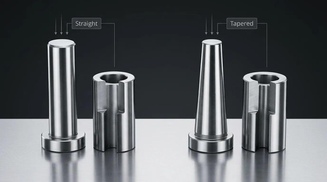
Positions droites et effilées en un coup d’œil
The comparison should cover the complete pin-and-bushing pair, not only the visible pin shape.
| Facteur de comparaison | Ensemble de positionnement en ligne droite | Ensemble de positionnement effilé |
|---|---|---|
| Géométrie de localisation | Surface de localisation parallèle ou cylindrique | Surface de localisation conique ou effilée |
| Comportement d’entrée | Entrée à un dégagement quasi constant | La garde au sol diminue progressivement lors de l’entrée |
| Exigence d’approche | Nécessite généralement un alignement préalable bien contrôlé | Peut capturer un décalage d’approche limité |
| Position finale | Déterminé principalement par l’ajustement et l’alignement de la goupille à la bague | Determined by taper geometry, seating position, and mating accuracy |
| Conditions de fermeture | Certains modèles nécessitent un jeu de ligne de séparation à la fermeture complète | Certains modèles peuvent être configurés pour un contact conique complet à la fermeture |
| Principal avantage | Controlled, repeatable pre-positioning | Introduction progressive et capture géométrique |
| Principale limitation | Peut se bloquer si des pièces rapprochées se détournent de l’axe | Peut se coincer ou développer un contact inégal si le saut est incorrect |
| Meilleur état d’ajustement | Système de guidage stable et approche de moule prévisible | Besoin d’une correction contrôlée lors de l’engagement final |
| Difficulté de la rénovation | Le remplacement doit préserver l’ajustement et la position de l’axe | Conversion requires review of taper, Sièges, Montage, and mating geometry |
A straight system is not merely a tapered system without an angle. The geometry changes how the components enter, where contact develops, and how positional error is transferred into the mold plates.
Comment chaque géométrie s’engage à mesure que le moule se referme.
The mold’s leader pins and guide bushings normally control the initial movement of the two mold halves. Positioning pins act later in the closing sequence, refining plate location before sensitive features make full contact.
Une séquence typique est:
- The leader pins enter their guide bushings and establish the general closing path.
- The positioning pin begins entering its mating bushing.
- The positioning set reduces the remaining lateral movement between the plates.
- Broches de noyau, Inserts, shutoffs, or other close-clearance features reach their final engagement.
- The mold reaches its designed closed condition.
This sequence matters because positioning components should normally control plate location before delicate features are forced to absorb misalignment. MISUMI’s mold-component documentation, par exemple, describes positioning sets intended to engage before core pins and also notes the need for an appropriate precision leader-pin system. Exact timing still depends on the specific mold design and selected component set.
La fonction de guidage principale appartient à Goupilles guides de moule. Positioning pins supplement that guidance near final closure; they should not be expected to correct a damaged guide system, severe platen movement, or major mold-base error.
Comment un ensemble de positionnement en ligne s’engage
A straight positioning pin enters a cylindrical mating bore. Because the locating surfaces remain parallel, the available entry clearance does not progressively increase toward the tip in the same way as a full tapered locating interface.
This makes prior alignment important. When the leader-pin system has already brought the mold plates close to their intended axes, a straight positioning set can provide controlled and repeatable pre-positioning. The final movement between the pin and bushing depends heavily on their specified fit.
The same close fit that improves positional control can also increase sensitivity to:
- Entrée hors axe
- Contamination dans la bague
- Bords endommagés ou surélevés
- Concentricité incorrecte
- Mouvement thermique ou structurel
- Points de localisation redondants qui contraignent trop les plaques
Some catalog straight positioning systems require a small parting-line clearance when the mold is fully closed. That requirement prevents the positioning components from unintentionally carrying closure load or interfering with full plate contact. It is product-specific and must be taken from the selected supplier’s drawing rather than treated as a universal value.
Comment un ensemble de positionnement effilé s’engage
A tapered pin enters a matching tapered bushing or seat. At the beginning of engagement, the smaller leading section provides more room for entry. As the mold continues to close, the available radial clearance decreases and the taper progressively guides the mating components toward a common axis.
This progressive capture is the main reason to consider a tapered system. It can tolerate a limited amount of initial offset that might cause edge contact in a close straight interface.
Final performance, cependant, depends on more than the presence of a taper. The designer must control:
- Angle de conique ou rapport de conique
- Position axiale des sièges
- Concentricité entre la localisation et le montage des éléments
- Durée des engagements
- Distribution des contacts
- Condition de ligne de rupture
- Méthode de rétention et de retrait
Some supplier systems can be arranged to reach full taper contact or zero clearance at mold closure. That behavior applies only to the documented design. It should not be generalized to every tapered positioning pin.
If the taper seats too deeply, uses incompatible mating angles, or enters under excessive offset, it may create wedging, Contact inégal, difficult release, or unwanted load on the mold plates.
Les critères de sélection qui déterminent réellement le meilleur choix
The pin shape should not be selected in isolation. The mold’s approach behavior and final positioning requirement are more important than a general preference for straight or tapered components.
| Critère de sélection | Le straight est généralement préféré quand... | Le tapered est généralement préféré lorsque... |
| Alignement de l’approche initiale | Le système de goupille de ligne de ligne contrôle déjà étroitement les axes | Le décalage d’approche limité doit être capturé progressivement |
| Exigence finale de position | Un ajustement cylindrique spécifié peut fournir le contrôle requis | L’emplacement final est déterminé par un système contrôlé de sièges effilés |
| Caractéristiques sensibles à la moisissure | Un prépositionnement est nécessaire avant que les noyaux ou les inserts ne s’engagent | Une correction progressive est nécessaire avant les arrêts ou le contact rapproché des caractéristiques |
| Sensibilité à l’entrée | L’entrée hors axe est minimale et prévisible | Un peu de prise d’entrée est nécessaire pour réduire le contact brusque des bords |
| Conditions de fermeture | Le jeu de jeu nécessaire pour les lignes de détachement ou de séparation peut être maintenu | Le comportement de seating complet peut être défini et contrôlé |
| Risques à gérer | Reliure et incisions | Enlèvement et contact réciel inégal |
| Contrôle de montage | Les axes de goupille et de bague peuvent être tenus avec précision | L’axe effilé et le siège axial peuvent tous deux être maintenus avec précision |
| Stratégie de remplacement | Le remplacement direct du cylindre est pratique | Une géométrie et un assis coniques adaptés peuvent être reproduits |
| Disponibilité des composants | Un ensemble droit standard approprié existe | Un ensemble de coniques standard approprié existe ou un design personnalisé est justifié |
The decision also depends on whether the required component exists as a standard catalog item. Where diameter, Effilage, Montage, Rétention, or engagement conditions fall outside standard ranges, a drawing-based part may be necessary. SunshinePro states that it supplies both standard components and non-standard mold parts processed from customer drawings. Its broader guidance on Moulage des pièces standard can help separate catalog selection from customization.
Quand un placement en ligne droite est le meilleur choix
A straight positioning system is generally the stronger candidate when the mold’s initial guidance is already stable.
Typical conditions include:
- The leader pins and guide bushings keep plate approach error low.
- The positioning set needs to establish a close, repeatable location before core pins engage.
- The designer can specify and inspect the cylindrical pin-to-bushing fit.
- Parting-line clearance requirements are known.
- Mounting bores and locating axes can be held concentric.
- Contamination and off-axis impact can be controlled.
- Replacement components can reproduce the original fit.
Consider a mold containing several delicate core pins that enter close-clearance holes near the end of closure. If the main guide system already brings the two mold halves into reliable alignment, a straight positioning set can refine their location before those core pins enter.
The design becomes less suitable when significant lateral error remains at the start of positioning engagement. A close straight fit should not be used as a substitute for correcting damaged leader pins, worn guide bushings, or mislocated mounting bores.
Quand un ensemble de positionnement effilé est le meilleur choix
A tapered positioning system is generally more appropriate when the mold needs a controlled lead-in before reaching its final position.
Typical conditions include:
- Limited approach variation remains after the main guide system engages.
- The mold needs progressive rather than abrupt correction.
- The taper can engage before sensitive shutoffs, Inserts, or cores reach contact.
- Taper angle, axial seating, and contact position can be defined accurately.
- The design can prevent excessive seating force.
- Removal access is available if the taper becomes tightly seated.
- The selected supplier can reproduce the complete mating geometry.
A tapered system may be useful when two plates approach with a small lateral offset that is acceptable at the start of engagement but must be reduced before a close shutoff meets its mating surface. The taper introduces correction gradually as engagement increases.
That does not mean a tapered pin can repair a poorly guided mold. Its capture range is limited by the actual geometry. Forcing a taper to correct excessive offset can concentrate load on one side of the pin and bushing, damage the contact surfaces, or shift stress into the surrounding mold plate.
Risques, Failure Modes, and Retrofit Mistakes
Straight and tapered systems fail in different ways, although both are sensitive to poor mounting, Contamination, Usure, and incorrect engagement order.
| Risque | Cause probable | Résultat possible | Réponse de conception |
| Reliure droite | Ajustement serré combiné à une entrée hors axe | Jamming, Score, plate damage | Améliorer les directives préalables et vérifier l’autorisation d’exploitation |
| Charge sur les bords | Une goupille mal alignée touche le bord de la bague | Tenue locale, Ébréchage, Déformation | Examinez le timing d’engagement et la localisation des axes |
| Effilage effilé | Assise axiale excessive ou géométrie de conique inadaptée | Difficult opening, unwanted preload | Définir avec précision l’arrêt axial et le rétrécissement d’accouplement |
| Contact déséquilibré | Angle, Concentricité, or mounting error | Usure localisée et mauvaise localisation finale | Inspecter la géométrie du conique et les datums de montage |
| Irritation ou incision | Poor finish, material pairing, Lubrification, ou contamination | Déplacement brusque et usure accélérée | Spécifier les surfaces de contact et les conditions de maintenance |
| Jeu d’usure induit | Contact répété et soutien insuffisant | Augmentation du mouvement positionnel | Définir les critères d’inspection et de remplacement |
| Contact prématuré des caractéristiques | Le set de positionnement s’engage trop tard | Damage to cores, Inserts, or shutoffs | Corrigez la séquence d’engagement |
| Élimination difficile des composants | Aucune fonction d’extraction ni accès arrière | Entretien plus long et risque de dommages sur la plaque | Incluez des robinets de démontage ou un accès de service planifié |
One of the most common design mistakes is treating straight and tapered positioning sets as interchangeable.
Changing a straight pin to a tapered pin affects the mating bushing, installation depth, axial seating, Motif de contact, parting-line condition, and removal method. The surrounding mold plate may also need different machining. A retrofit should therefore be reviewed as a system change, not a simple pin substitution.
L’inverse est également vrai. Replacing a tapered system with a straight fit may remove the original lead-in and make the mold more sensitive to approach error.
Ce que le dessin et la RFQ doivent spécifier
A supplier cannot evaluate a positioning system accurately from pin diameter alone. The drawing or request for quotation should define the complete mating arrangement.
Incluez:
- Géométrie de positionnement droite ou effilée
- Dimensions de la goupille et de la bague
- Durée des engagements
- Taper angle or ratio, Lorsque cela est applicable
- Ajustement prévu ou condition finale de l’assise
- Espace de départ requis
- Côtés de fixation de goupilles et de bagues
- Retention method
- Siège axial ou emplacement de butée
- Prise de démontage ou accès d’extraction
- Exigences en matière de matériaux
- Traitement thermique et exigences de dureté
- Exigences de finition de surface
- Concentricité critique et tolérances dimensionnelles
- Quantité
- Exigence de remplacement en ensemble assorti ou interchangeable
- Dimensions d’inspection
- Exigences relatives au rapport d’inspection
- Relevant operating temperature, Contamination, Chargement, or maintenance conditions
The pin and bushing should be treated as a mating system. Ask whether replacement components are individually interchangeable or whether the supplier expects them to remain a matched pair.
Detailed tolerance selection belongs in the component drawing and supplier review. Generic fit assumptions are risky because a straight sliding fit, a close positioning fit, and a fully seated taper behave differently during mold closure.
SunshinePro states that it can process non-standard mold parts from customer drawings. The company also describes raw-material inspection, Surveillance en cours de processus, Essais finaux, and inspection reporting on its quality page. Those statements support asking about drawing review and critical inspection dimensions, but the exact process, Tolérance, Matériel, and report for a specific positioning set still need written confirmation.
Règle de sélection finale
Choose a straight positioning set when the mold already has controlled approach guidance and needs close, repeatable pre-positioning.
Choose a tapered positioning set when limited approach offset must be captured progressively and the taper’s seating condition can be controlled.
Review another alignment solution when the mold has severe lateral movement, damaged guide components, major platen problems, or loads beyond what a positioning set should correct.
The better design is the one that matches the complete closing sequence, not the pin shape that appears more precise in isolation.
Préparation d’un dessin de composante de positionnement pour l’examen du fournisseur
Avant de demander un devis, prepare a drawing that shows both sides of the mating system and identifies the functional datums. Include the mold-closing direction, engagement position, final closure condition, and any sensitive features that must be protected before contact.
A useful supplier submission should contain:
- Les dessins de goupille et de bague
- Les détails de montage pertinents sur la plaque de moulage
- Required fit, Dégagement, or taper seating
- Matériel, Dureté, Fin, et exigences d’inspection
- Conditions de remplacement et d’interchangeabilité attendues
SunshinePro offers standard and tailored mold-component solutions and accepts drawing-based non-standard part inquiries. For a straight or tapered positioning system, Utiliser le Page de contact to submit the complete mating design and request confirmation of manufacturability, critical inspection points, et stratégie de remplacement.
Partager:


Écrit par Sunshine
Au soleil, Nous sommes un fabricant et fournisseur professionnel de composants de moule de précision, proposant une large gamme de produits pour les applications de stampage et de moulage par injection. Notre objectif principal est le poinçage des coins, Goupilles et manchons d’éjection, et poteaux guides et bagues. Avec un usinage CNC avancé, Contrôle qualité strict, et de fortes capacités de production, Nous garantissons une fiabilité, Pièces de haute précision, ainsi que des composants standards en stock pour un approvisionnement mondial rapide et efficace.
ACTUALITÉS
OBTENIR UN SERVICE
Avec des pièces de qualité adaptées à tous les budgets et un personnel accueillant formé pour rendre votre visite informative et sans tracas.
