



Désalignement de la goupille de positionnement du moule: Symptômes et dépannage
Mold positioning pin misalignment can cause binding during closure, Contact inégal, parting-line mismatch, Flash, abnormal wear, or inconsistent part dimensions. The pin itself may be damaged, but it is only one possible cause. A worn bushing, loose mounting bore, contaminated parting surface, damaged interlock, Croissance thermique, poor mold installation, or machine-platen condition can create similar symptoms.
The correct approach is to identify when the problem occurs, inspect the entire mating system, measure the suspected geometry, and repair only the verified cause. For broader information about component fit, Usure, Matériaux, et lubrification, see SunshinePro’s guide to Broches et bagues de moulage (déduit).
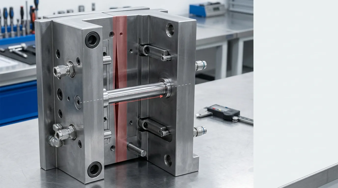
Vérifiez d’abord ce que fait la « goupille de positionnement » dans ce moule
“Positioning pin” is not used consistently across every mold design. Before troubleshooting, identify the component by function rather than relying only on its name.
| Composant | Rôle principal | Implications diagnostiques |
|---|---|---|
| Localisation ou goupille à chevilles | Établit une position répétable entre les composants ou les plaques | Check its geometry, Ajustement de montage, Orientation, and mating hole or bushing |
| Épingle guide, leader pin, or guide pillar | Guider les moitiés du moule pendant l’engagement | Vérifiez la droiture, Usure, bushing clearance, and side-loading marks |
| Douille de guidage ou de localisation | Reçoit la broche et contrôle l’interface d’accouplement | Check bore wear, ovality, Poste, Rétention, and entry damage |
| Verrouillage latéral ou verrou effilé | Aide à établir ou à maintenir l’enregistrement final de la moisissure | Check contact pattern, Usure, Dégâts, et engagements |
| Coupure ou surface d’accouplement de précision | Contribue à l’alignement final et à l’étanchéité | Check for impact marks, Désaccord, local gaps, and edge damage |
A guide pin may control the initial closure path while another locating feature controls final core-to-cavity registration. Replacing the guide pin will not solve the problem if the final interlock, Silent, mounting bore, or mold plate is out of position.
Guide séparé de SunshinePro pour Goupilles guides de moule covers broader guide-pin function, Usure, and selection. Tiens, the focus is determining why an installed mold is no longer aligning correctly.
Symptômes qui indiquent un problème d’enregistrement de moisissure
The timing and location of a symptom often provide more useful evidence than the symptom alone.
| Symptôme | Quand il apparaît | Sous-système possible | Première vérification de confirmation |
| Binding au même endroit pendant la fermeture | Fermeture à froid ou sans charge | Bent pin, skewed bushing, damaged interlock, Meule, or plate-position error | Arrêtez-vous au premier point de contact et inspectez la présence de marques de témoins unilatérales |
| Scraping, Vibration, or impact noise | Lors de l’engagement par goupille ou verrouillage | Chargement latéral, insufficient clearance, Contamination, or damaged entry geometry | Inspect the pin, bushing mouth, interlocks, and nearby surfaces |
| Chaleur anormale près du système de guidage | Après plusieurs cycles | Friction, Mauvaise lubrification, tight fit, Chargement latéral, or galling | Vérifier le score, discoloration, Condition du lubrifiant, and uneven contact |
| La moisissure ne se referme pas de façon ferme | Installation ou fermeture contrôlée | Mounting error, Obstruction, Distorsion de la plaque, machine-side alignment, or damaged positioning components | Inspect mounting, Caractéristiques de localisation, parting surfaces, and plate relationships |
| Pas de ligne de séparation ou décalage | Pendant la production | Registration loss, Mouvement des plaques, interlock wear, or machine-side loading | Comparez l’emplacement du décalage avec les contacts et les motifs d’usure |
| Éclair localisé | Sous pression d’injection | Misregistration, damaged shutoff, insufficient clamping, Contamination, or process conditions | Vérifiez si la moisissure s’aligne sans pression et inspectez l’arrêt affecté |
| Variation dimensionnelle entre les cycles | Après échauffement ou sous charge | Changing clearance, Croissance thermique, Mouvement des plaques, or worn positioning features | Compare cold, warm, and production-condition measurements |
| Polissage à goupille ou bague à un seul côté | Progressif au fil du temps | Mispositioned bore, bent pin, plate error, or uneven machine loading | Mesurez le décollement des goupilles et inspectez la position et la perpendicularité de l’alésage |
DME’s technical guidance on mold interlocks identifies flash, dimensional problems, and component damage as possible consequences of improper mold alignment. It also notes that worn leader pins and bushings, thermal variation, mold weight, and equipment condition can affect registration. See DME’s Conseils techniques sur l’alignement des moules.
Flash alone does not prove positioning pin failure. Flash can also result from damaged shutoffs, trapped material, insufficient clamping, Pression excessive, or other tooling and process conditions. Treat it as evidence that requires further inspection.
Symptômes lors de la fermeture de la moisissure
Closure-related symptoms usually point toward the engagement path.
Cherchez:
- Resistance that begins at the same position during each closing attempt.
- A pin entering the bushing off-center.
- Fresh contact marks on only one side of the pin.
- Scraping at the bushing entrance.
- Impact marks on interlocks or shutoffs.
- A visible gap on one side of the parting line.
- A pin, Silent, or retainer moving in its mounting feature.
A repeatable hard-contact point is more likely to involve geometry, Obstruction, or mounting position than a process-setting problem.
Symptômes sur la partie moulée ou la surface de séparation
Production evidence may include:
- A step across the parting line.
- Flash concentrated in one region.
- Uneven witness lines.
- Chipping or peening near a precision shutoff.
- Dimensional changes after the mold reaches operating temperature.
- Parts that shift in one direction under pressure but appear acceptable during an unloaded closure check.
These symptoms help locate the affected region, but measurements are still needed before deciding which component to repair.
Arrêtez de faire circuler la moisissure lorsque les dommages sont probables
Do not continue closing the mold to “see if it clears” when there is evidence of hard interference or displaced components.
Stop and establish a safe inspection condition when you find:
- A visibly bent or loose pin.
- A cracked, pucé, or displaced bushing.
- Metal fragments or severe scoring.
- Fresh impact damage on a core, cavité, Insertion, shutoff, or interlock.
- Sudden hard resistance during closure.
- A plate or component moving inside its mounting feature.
- An engagement path that cannot be confirmed safely.
Injection molding machines can expose technicians to crushing, stored hydraulic energy, electrical energy, hot surfaces, and moving components. Inspection and servicing should follow the machine manufacturer’s instructions, the facility’s hazardous-energy procedure, and applicable local regulations. Les États-Unis. Occupational Safety and Health Administration provides general guidance on Risques des machines à moulage par injection horizontale et control of hazardous energy.
Dépanner le désalignement dans un ordre fixe
A consistent sequence reduces unnecessary disassembly and prevents one symptom from being mistaken for proof of pin failure.
- Review when the problem started.
Determine whether the change was sudden or progressive. Check whether it began after maintenance, Remplacement des composants, mold transfer, machine setup, a cooling change, or warm-up. - Place the machine and mold in an approved safe inspection condition.
Isolate hazardous energy before entering the mold area or touching components that could move. - Clean exposed interfaces.
Remove trapped plastic, Puces, meules, contaminated lubricant, and other debris from the parting line, pin entries, Silents, and interlocks. - Inspect the pin, Silent, Montage, et la rétention.
Look for looseness, Score, impact marks, Polissage inégal, Déplacement, or damaged fasteners. - Observe the engagement pattern.
Under an approved controlled procedure, identify which component contacts first and whether the contact is centered or one-sided. - Measure the suspected geometry.
Check pin and bushing dimensions, runout, Condition du canon de montage, component position, and plate relationships. - Separate mold-side causes from machine-side and thermal causes.
Compare cold and warm behavior, unloaded and production-loaded behavior, and results across machines when practical. - Correct the verified cause.
Clean, adjust, Réparation, or replace only after the inspection evidence supports that action. - Validate the repair.
Confirm smooth engagement, stable registration, correct parting-line contact, and acceptable molded-part results.
Enregistrez quand le problème a commencé
The failure history can quickly narrow the investigation.
A sudden problem after maintenance may indicate:
- A reversed or incorrect replacement component.
- A bushing or pin installed at the wrong depth.
- A burr created during assembly.
- A loose retainer or fastener.
- A plate assembled out of position.
Progressive deterioration more often suggests:
- Increasing pin or bushing wear.
- Lubrication breakdown.
- Mounting-bore damage.
- Plate movement.
- Repeated side loading.
- Thermal or machine conditions that gradually accelerate wear.
A problem that appears only after moving the mold to another machine should trigger checks of mold installation, locating-ring engagement, platen condition, and clamping alignment before replacing mold components.
Commencez par le nettoyage et l’inspection non destructive
Begin with checks that do not alter the mold:
- Clean pin surfaces and bushing entrances.
- Remove plastic residue from the parting line.
- Inspect for burrs around bores and interlocks.
- Check retainers and fasteners for movement.
- Mark and photograph contact patterns.
- Compare the left and right sides of the mold.
- Check whether the pin enters the bushing concentrically.
Cleaning may restore movement when debris is the only obstruction. It does not prove that the pin, Silent, or plate geometry remains within specification.
Inspectez la goupille, Silent, and Mounting Features as One System
A positioning pin does not work independently. Its performance depends on the mating bushing or hole, the mounting bore, the mold plate, and any final-positioning features.
Indices de défaillance côté broche
Evidence that directly implicates the pin includes:
- Measurable bending or runout.
- One-sided scoring along the engagement length.
- Impact damage at the leading end.
- Mushrooming or chipped edges.
- A loose shank or failed retaining feature.
- Incorrect installed height.
- Geometry that does not match the drawing.
- Contact concentrated in one region rather than distributed as intended.
One-sided polishing can indicate a bent pin, but it can also result from a mispositioned bushing or mounting bore. Confirm the pin’s straightness before assigning the cause.
Silent- and Bore-Side Failure Clues
Inspect the mating side for:
- Uneven or oval bore wear.
- A loose bushing.
- Damage at the entry chamfer.
- Scoring concentrated on one side.
- A bushing installed out of position.
- Cracks or deformation around the mounting feature.
- A damaged press-fit bore.
- Burrs that prevent the bushing from seating correctly.
Replacing a worn pin while leaving an oval or loose bushing in place may restore movement temporarily without restoring repeatable registration. The mating pair and both mounting features should be evaluated together.
Mesurez la géométrie avant de choisir une réparation
Visual inspection identifies where to investigate, but dimensional evidence should determine whether a component is acceptable.
Measure as applicable:
| Caractéristiques | Pourquoi cela compte | Base d’acceptation |
| Diamètre de goupille à plusieurs positions | Reveals taper, localized wear, or material loss | Dessin de moule approuvé ou spécification des composants |
| Alésage de la bague à plusieurs orientations | Identifie un jeu excessif ou une usure ovale | Dessin, supplier specification, or applicable standard |
| Rectitude des goupilles ou runout | Détecte la flexion provoquant un contact latéral progressif | Dessin ou procédure d’inspection approuvée |
| Position de la goupille et de la bague | Détermine si leurs axes s’alignent | Dessin de moule et structure de référence |
| Perpendiculité à la plaque | Identifie l’installation inclinée ou l’erreur d’alésage | Dessin ou spécification technique |
| Condition du calibre de montage | Détermine si le composant est correctement supporté et conservé | Dessin et critères de réparation approuvés |
| Relation de plaque | Detects shift, Distorsion, or movement between assemblies | Plan d’assemblage et d’inspection du moule |
Do not apply one universal pin-to-bushing clearance or wear limit to every mold. The correct value depends on the component design, Taille, Fonction, supplier series, Température de fonctionnement, and required positioning accuracy.
For standardized components within their stated scope, ISO 8017 covers dimensions and tolerances for specified guide pillars and locating guide pillars. ISO 8018 covers specified headed guide and locating guide bushes. These standards do not replace the approved mold drawing, and they should not be applied to components outside their scope.
Record the measurement reference, Instrument, Mise en place, Révision du dessin, and actual results. A list of numbers without the measurement method may not be sufficient for repair or replacement decisions.
Causes distinctes côté moule des effets de la machine et de la température
The same mold symptom can originate outside the pin-and-bushing pair.
Ask:
- Did the problem begin after installing the mold on a different machine?
- Does the mold align when cold but bind after warm-up?
- Does it close smoothly without pressure but shift during production?
- Is one mold half operating at a different temperature?
- Are the locating ring and mounting surfaces seated correctly?
- Are the platens, Pinces, or tie system applying uneven load?
- Do interlocks show contact only after pressure is applied?
- Does the problem disappear when the mold is checked outside the original machine?
Désalignement froid vs chaud
A mold may close correctly at room temperature and begin binding after thermal stabilization. Unequal heating changes the dimensions of plates, bores, Quilles, Silents, and interlocks. The pin may appear to be the problem even though the underlying cause is differential thermal growth.
Compare:
- Cold engagement.
- Engagement during warm-up.
- Stable operating-temperature engagement.
- Temperatures on both mold halves.
- Cooling conditions near the affected region.
- Contact marks before and after warm-up.
Do not assume the pin changes independently of the surrounding plate. The entire alignment chain expands and moves together.
Désalignement sans charge versus sous-pression
Smooth unloaded closure does not guarantee stable registration during production.
If misalignment appears only under injection or clamping load, Inspecter:
- Side interlocks and taper locks.
- Plate support and fasteners.
- Shutoff contact.
- Mold mounting.
- Platen condition.
- Locating-ring engagement.
- Load-sensitive movement between plates.
Changing pressure, Vitesse, or clamping settings may reduce the visible defect, but it does not correct a mechanical positioning error.
Associer l’action corrective à la cause vérifiée
| Cause vérifiée | Action appropriée | Contrôle supplémentaire |
| Trapped plastic, Puces, or removable debris | Nettoyez les surfaces affectées | Confirmez qu’il ne reste ni meule ni dommage permanent |
| Lubrifiant approuvé contaminé ou manquant | Nettoyez et restaurez l’état de lubrification spécifié | Inspect for existing scoring, Usure, or galling |
| Bent, worn, or impact-damaged pin | Remplacez-le par un composant correspondant au dessin approuvé | Inspectez la bague et l’alésage de fixation |
| Silent usé ou ovale | Remplacer ou réparer selon la conception du moule | Confirmez l’état de la goupille et la dégagement réel de l’accouplement |
| Goupille ou bague desserrée | Corrigez la fonction de rétention ou de montage grâce à une réparation agréée | Vérifiez si l’alésage ou la plaque est endommagé |
| Alésage de fixation endommagé | Réparez l’alésage ou la plaque affectée avant d’installer un nouveau composant | Rétablir la position et la perpendicularité |
| Interverrouillage ou coupure usé | Réparer ou remplacer la fonction de positionnement final affectée | Confirmez que les composants du guide n’ont pas été installés en side-loading |
| Erreur d’installation ou d’anneau de localisation | Montage et centrage corrects du moule | Revérifier la fermeture et le contact de la ligne de séparation |
| Chargement côté machine ou problème en plaques | Suivez le processus d’inspection et de réparation du fabricant de machines | Confirmez que la moisissure n’a pas subi de dommages secondaires |
| Distorsion thermique | Corrigez le déséquilibre vérifié de température ou de refroidissement | Valider l’alignement à une température de fonctionnement stable |
Lubrication can reduce friction. It cannot straighten a bent pin, correct a misplaced bore, restore an oval bushing, or realign a distorted plate.
Do not install a new pin into a damaged bore simply because the replacement fits initially. If the mounting feature cannot hold the component at the required position and angle, the new part may fail quickly or reproduce the same alignment error.
Validez l’alignement avant de remettre le moule en production
After correction, validate the complete system rather than checking only whether the mold can close once.
Use the machine manufacturer’s approved procedure to confirm:
- Smooth and repeatable engagement.
- No abnormal impact, scraping, Vibration, or resistance.
- No new scoring or concentrated witness marks.
- Correct parting-line and shutoff contact.
- Stable pin and bushing temperatures.
- No movement at retainers or mounting features.
- Consistent behavior after the mold reaches operating temperature.
- Stable registration under approved production conditions.
- Acceptable molded-part dimensions.
- No abnormal flash or parting-line step.
Recheck critical dimensions when a pin, Silent, Calibre, Plaque, or interlock has been repaired. Record what was changed, the measurements taken, and the validation result. One successful closing cycle is not sufficient evidence of long-term correction.
Préparez des informations complètes de remplacement lorsqu’un composant est hors spécifications
Once inspection confirms that a positioning pin, guide component, or bushing requires replacement, provide the supplier with enough information to reproduce the intended geometry rather than the worn condition.
Préparez-vous:
- The approved component drawing and revision.
- The component’s function: Localisation, Guidage, or final positioning.
- Pin and mating-bushing dimensions.
- Mounting and retention details.
- Required fit and tolerances.
- Matériel, Dureté, Traitement thermique, and surface requirements stated on the drawing.
- Quantité.
- The worn sample, when useful and available.
- Photographs or notes showing the failure pattern.
- Confirmation of whether the mating component or mounting bore will also be repaired.
- Documentation d’inspection requise.
SunshinePro indique qu’il propose des modèles personnalisés standards et basés sur le dessin Moulage des pièces standard, including guide components and dowel pins. The company also lists locating-pin guide bushings and describes inspection processes for custom components.
After the failed component and its mating conditions have been measured, the next practical step is to Soumettre les exigences de dessin et de remplacement pour la revue. The request should describe the verified failure and required geometry rather than asking a supplier to reproduce an unmeasured worn sample.
Partager:


Écrit par Sunshine
Au soleil, Nous sommes un fabricant et fournisseur professionnel de composants de moule de précision, proposant une large gamme de produits pour les applications de stampage et de moulage par injection. Notre objectif principal est le poinçage des coins, Goupilles et manchons d’éjection, et poteaux guides et bagues. Avec un usinage CNC avancé, Contrôle qualité strict, et de fortes capacités de production, Nous garantissons une fiabilité, Pièces de haute précision, ainsi que des composants standards en stock pour un approvisionnement mondial rapide et efficace.
ACTUALITÉS
OBTENIR UN SERVICE
Avec des pièces de qualité adaptées à tous les budgets et un personnel accueillant formé pour rendre votre visite informative et sans tracas.
