



Tolérance et concentricité de la goupille de perforation pour un estampage stable
Punch pin tolerance and concentricity affect more than the measured diameter of a component. A punch point can meet its size tolerance and still sit off-center relative to the shank, Serviteur, or die opening. That error changes local punch-to-die clearance and can lead to uneven loading, Usure, Variation des meules, Déviation, or premature damage.
The punch must therefore be evaluated as part of a complete locating system. The shank fits into the retainer, the point enters the die opening, and the surrounding die components maintain alignment during each stroke. The broader roles of these parts are covered in SunshinePro’s Guide des composants de la puce (déduit). This guide focuses specifically on how punch dimensions, geometric relationships, drawing controls, and inspection methods support stable stamping.
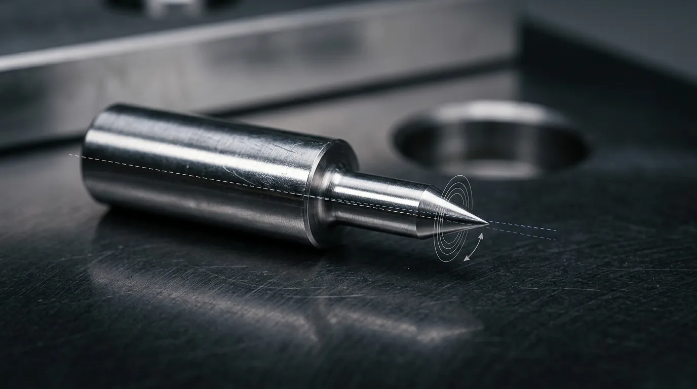
Quelle tolérance aux goupilles de perforation contrôle réellement
A dimensional tolerance defines how much a stated size may vary. On a punch pin, separate tolerances may apply to:
- Diamètre de pointe de pointe ou profil de coupe
- Diamètre de la tige
- Longueur totale
- Longueur du point
- Position de l’épaule
- Caractéristiques de tête ou de rétention
A geometric tolerance controls something different. It may limit the form of one feature, the orientation or location of one feature relative to another, or the variation of a surface when the part rotates around a datum axis.
This distinction matters because size tolerance does not automatically control alignment.
A punch point and shank may both be within their specified diameter limits while their centerlines remain offset. The shank may also be slightly bent, the point may be ground at an angle, or a cylindrical surface may be out of round. None of those conditions is fully described by diameter tolerance alone.
Pourquoi la seule tolérance au diamètre ne suffit pas
Consider a stepped punch with a locating shank and a smaller cutting point. Each diameter can be acceptable when measured independently. Cependant, if the point axis is offset from the shank axis, rotating the punch around the shank will cause the point surface to move toward and away from the indicator.
The punch is within size tolerance, but it may not remain centered in the die opening.
The drawing must therefore answer two separate questions:
- Is each feature the correct size?
- Is each feature in the correct geometric relationship to the functional reference?
That reference is often the shank or another locating feature that represents how the punch is installed in the retainer.
Concentricité, Coaxialité, Runout, and Position Are Not Interchangeable
“Concentricity” is often used informally to describe how well the punch point aligns with the shank. In formal geometric dimensioning and tolerancing, cependant, the word can have a more specific meaning.
The applicable drawing standard must be identified before deciding which term or control is correct. ASME Y14.5 defines dimensioning and tolerancing practices for drawings governed by the ASME system. ISO 1101 provides the geometrical-specification framework used on ISO-based drawings.
| Terme ou contrôle | Ce qu’il décrit | Pertinence pratique du punch | Risque d’interprétation courante |
|---|---|---|---|
| Concentricité | A relationship between centers or derived median points relative to a datum axis, depending on the governing standard | Peut apparaître sur des dessins anciens ou contrôlés par le client | Souvent confondu avec une simple lecture d’indicateur |
| Coaxialité | La condition de deux caractéristiques partageant l’axe prévu | Concept utile pour l’alignement point-tige | Peut être utilisé de façon descriptive sans définition complète du dessin |
| Excentricité | Décalage physique entre des centres ou axes nominalement communs | Décrit à quel point le point de punch est déplacé par rapport à la référence du shank | Il faut préciser si la valeur rapportée est un décalage radial ou un mouvement complet de l’indicateur |
| Runout circulaire | Variation de surface mesurée à chaque section circulaire lors d’une rotation autour d’un axe de référence | Utile pour contrôler la variation locale de rotation | Inclut plus que le décalage central car la forme de surface influence aussi la lecture |
| Totalité des éliminations | Variation cumulative de surface sur une longueur contrôlée pendant la rotation | Utile lorsque la relation complète de surface cylindrique compte | Cela peut être inutilement restrictif si une seule section est fonctionnellement importante |
| Poste | Emplacement d’un élément ou d’un axe de caractéristique par rapport aux datums définis et aux dimensions de base | Peut être approprié pour localiser les caractéristiques de la poinçonnette ou de la matrice | Ne contrôle pas automatiquement toute variation de surface |
| Profil | Taille, Forme, Emplacement, and sometimes orientation of a contour | Important pour les coups non coups de poing non rounds | Le centrage seul ne contrôle pas le profil de coupe complet |
A dial indicator normally reports surface displacement during rotation. That result is commonly expressed as runout or total indicator reading, or TIR. It is not automatically equivalent to formal GD&T concentricity.
Le Institut national des normes et de la technologie explains that runout controls can reflect both axis-related displacement and surface-form effects. An indicator reading may therefore include eccentricity, roundness error, fixture error, Défauts de surface, and the way the datum is simulated.
Pourquoi la norme de dessin et la révision sont importantes
A geometric callout has meaning only within its governing standard and revision. A legacy customer drawing may use concentricity differently from a newly created ASME-based drawing. An ISO-controlled drawing may also use a different specification framework.
Do not silently replace one control with another because it is easier to inspect. The designer, Fournisseur, and inspector should agree on:
- La norme et la révision qui régissent
- La caractéristique de référence
- La fonction contrôlée
- La limite numérique
- La méthode d’inspection
- La convention de reporting
Comment la chaîne de tolérance Punch–Retainer–Die affecte l’alignement
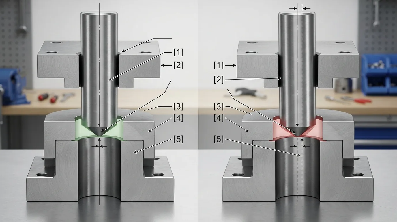
Punch alignment is not determined by the punch alone. Several component relationships contribute to the final location of the cutting point:
- The retainer hole positions and supports the punch shank.
- The shank establishes the punch’s installed reference.
- The punch point may be offset or angled relative to the shank.
- The die opening may be offset from the die-button body.
- The punch retainer and die button must be positioned correctly within the die assembly.
Each component may be acceptable individually while the combined assembly produces excessive error at the cutting interface.
Par exemple, a punch point may shift slightly in one direction relative to the shank. The die opening may also shift in the opposite direction relative to the die-button body. Those deviations add together and reduce clearance severely on one side.
In another assembly, the two offsets may partially cancel. That does not make the design reliable. Relying on accidental cancellation creates inconsistent results between replacements, sharpening cycles, or production batches.
Alignement point-à-tige
Point-to-shank alignment describes the relationship between the cutting point and the locating shank. A complete requirement should define more than a single “concentricity” number.
The drawing or inspection plan should identify:
- La surface de tige établit la référence
- Le diamètre ou le profil du point est contrôlé
- L’emplacement axial où le point est mesuré
- Whether the value represents radial eccentricity, circular runout, total runout, or TIR
- Si la longueur totale du point ou une seule section transversale est évaluée
Measurement location matters. A small angular error may produce little displacement near the shoulder but a much larger offset at the end of a long point. Small-diameter or slender punches are especially sensitive because lateral force can produce additional working deflection.
Pourquoi les erreurs d’alignement déstabilisent le processus d’emboutissage
Punch-to-die clearance is the space between the punch cutting edge and the die opening. It should be appropriate for the work material, épaisseur, operation, et conception des outillages. This article does not calculate that clearance, but the geometric relationship determines whether the intended clearance is distributed uniformly.
If the punch shifts toward one side of the die opening:
- L’espace deviennent plus petits du côté proche
- Le dégagement devient plus grand du côté opposé
- La charge de coupe commence et se développe de manière inégale
- La force latérale peut agir sur le coup de poing
- Le poinçon peut se déformer davantage sous charge
Conseils détaillés pour l’industrie de Tipco discusses how punch, le, and retainer eccentricity can combine to create non-uniform clearance and unbalanced loading. The exact result depends on punch proportions, Soutien, La condition, Matériel, et conditions de fonctionnement.
Possible symptoms include one-sided wear, uneven burrs, rubbing marks, repeated chipping on the same side, and shortened maintenance intervals. Misalignment may also contribute to fracture, Mais ce n’est qu’une cause possible. Sélection des matériaux, Traitement thermique, Dégagement, Force de dépouillage, Condition d’arête, lubrication, and punch design also matter. Those broader causes are addressed in Cassure de la poinçon dans les matrices d’emboutissage.
Which Geometric Controls Belong on a Punch Drawing?
The correct control begins with a functional question: what must remain aligned, and relative to which locating feature?
| Exigences fonctionnelles | Fonctionnalité impliquée | Direction de contrôle possible | Ce que cela ne garantit pas |
| Maintenir la taille du point de pointage | Diamètre ou profil de la pointe | Tolérance de taille ou exigence de profil | Alignement avec la tige |
| Maintenir l’ajustement de la tige | Diamètre de la tige | Taille et tolérance à la taille | Rectitude ou emplacement du point |
| Point d’alignement avec la tige | Point relatif au datum de tige | Runout, Poste, or another agreed geometric requirement | Emplacement correct du bouton de dé |
| Flexion limite ou dérive des axes | Axe de tige ou de point | Droit ou contrôle de forme associé | Position d’assemblage correcte |
| Contrôler la surface cylindrique complète pendant la rotation | Surface ponctuelle ou de tige | Épuisement total ou autre contrôle sur toute la surface | Adéquation de la limite numérique |
| Localiser un profil sculpté | Contour de coupe non rond | Profil et position par rapport aux datums | Orientation rotationnelle sauf indication |
| Empêcher la rotation du profil | Caractéristique de poinçonne façonnée | Exigence de verrouillage ou d’orientation | Centrage par lui-même |
The datum should normally represent the feature that locates the punch in service. If the shank is retained by a precision bore, the shank may provide the functional reference. Other punch designs may require a different datum structure.
The chosen requirement must also be inspectable. A control that cannot be measured consistently may create disagreement without improving the die.
Coups de poing ronds
For a round stepped punch, the drawing may need to control:
- Diamètre du point
- Diamètre et ajustement de la tige
- Relation point-à-poignard
- Droiture du pied
- Longueur du point
- Runout à un plan de mesure spécifié
A single runout value without a datum or axial location remains incomplete.
Coups de poing façonnés et non ronds
A non-round punch needs more than center alignment. The cutting profile may require control of:
- Forme et taille
- Position relative à la tige
- Orientation rotationnelle ou horloge
- Rayon d’angle
- Longueur du point
- Relation de bordure aux caractéristiques de rétention
SunshinePro affirme qu’elle produit des dessins basés sur le dessin Poinçons façonnés sur mesure and lists profile grinding and wire EDM among the processes used for relevant custom geometries. Actual tolerance feasibility still depends on the drawing, Profil, Matériel, Dimensions, et plan d’inspection.
Comment inspecter l’alignement et le runout des poinçons
An inspection result is meaningful only when the setup matches the drawing requirement.
The inspection plan should define:
- Référence ou surface de support
- Fonction contrôlée
- Position de mesure
- Instrument et dispositif
- Méthode de rapport
- Résolution des instruments
- Limite d’acceptation
- Révision du dessin applicable
Different setups can produce different results because they do not establish the same practical reference.
| Méthode d’inspection | Utilisations appropriées | Principales limitations |
| Dial indicator with V-blocks, centers, or a dedicated fixture | Vérifications pratiques de pointage ou de déroulement de la tige | Results depend on support, Position de contact, Propreté, Rondeur, et technique opératrice |
| Machine à mesurer les coordonnées | Axis, Centre, Poste, and complex feature relationships | Results depend on probing strategy, datum construction, Logiciels, and uncertainty |
| Comparateur optique ou système de vision | Diamètres de petits points, Profils, Orientation, et géométrie des arêtes | Edge detection, magnification, Fixation, and focus affect results |
| Système de mesure de la rondeur | Séparation détaillée de la forme et de la variation rotationnelle | Peut être inutile pour une acceptation de routine et nécessite une installation appropriée |
Guidage de mesure de Keyence describes both indicator-based and coordinate-measurement approaches and highlights the influence of contact and operator variation. ZEISS also distinguishes center-based and axis-based geometric relationships.
Indicateurs de cadran et contrôles TIR rotatifs
A practical rotational check usually follows this sequence:
- Clean the punch and fixture contact surfaces.
- Support or locate the shank using the agreed setup.
- Place the indicator at the defined point location.
- Rotate the punch through a complete revolution.
- Record the maximum and minimum readings.
- Report the full indicator variation or convert it only if the drawing defines another convention.
The setup must state whether the reported value is full TIR or radial eccentricity. Treating the two as the same can create a two-to-one interpretation error.
CMM, Optical, and Roundness Measurement
A CMM may be appropriate when the drawing controls axes, Position des caractéristiques, or complex datum relationships. Optical systems are useful for small points and shaped profiles where contact measurement is difficult. Roundness equipment can provide more detailed form information when indicator readings must be separated into roundness and axis-related components.
None of these methods is automatically correct for every punch. The method must match the characteristic being controlled.
Quand réinspecter une poinçonne
Reinspection is appropriate after:
- Affûtage ou rectification
- Écaillage ou usure anormale à sens unique
- Un blocage de presse ou une collision
- Changements soudains de motif de meules
- Remplacement d’un bouton de poinçonnage ou de dé
- Preuve de frottement contre l’ouverture du dé
- Différences inattendues entre les composants anciens et les composants de remplacement
Regrinding removes material from the punch point and changes point length. It may also expose profile or alignment errors that were not visible during earlier inspection.
Lorsque des tolérances plus strictes sont justifiées
The smallest available tolerance is not automatically the best specification. Tighter control is more likely to be justified when the application has:
- Petit espace disponible pour la mise à puce
- Coups de poing longs ou fins
- Diamètres de petits points
- Arrangements de poinçons en espace rapproché
- Profils non ronds avec des exigences strictes de localisation
- Exigences élevées d’interchangeabilité
- Volume de production élevé
- Exigeant la consistance de meule ou de bord
- Soutien latéral limité
Tighter tolerances increase manufacturing and inspection difficulty. They may require additional grinding operations, more stable fixturing, slower inspection, or more capable measurement equipment.
A practical requirement balances four factors:
- Besoin fonctionnel
- Capacité de fabrication
- Capacité d’inspection
- Coût de la défaillance versus coût du contrôle
SunshinePro’s punch product pages publish selected dimensional capability figures, including up to ±0.002 mm on its Page Punch Pin and a concentricity figure up to 0.003 mm on one other product page. These are product-page capability statements, not universal design values. Applicability should be confirmed for the required diameter, point length, Profil, Matériel, Quantité, et méthode d’inspection.
Readers needing broader die selection, Matériel, Dégagement, and sourcing context can refer to the Guide des matrices de poinçon.
Symptômes qui devraient déclencher un contrôle d’alignement
| Symptôme | Cause possible liée à l’alignement | Vérifications à effectuer |
| La meule augmente principalement d’un côté | Dégagement local inégal | Check punch-point position, die-opening location, Usure, et l’état des arêtes |
| Un côté du poinçon s’use plus vite | Contact latéral ou chargement décalé | Mesurez la dépression point à la tige et inspectez l’ajustement du dispositif |
| Des écaillages répétés se produisent au même endroit | Surcharge locale ou dégagement insuffisant | Inspect punch and die geometry, Dégagement, Matériel, and support |
| Le punch frotte l’ouverture du dé | Axis offset, bent punch, or component-location error | Vérifiez la droiture, runout, retainer position, and die-button alignment |
| La poinçon de remplacement se comporte différemment | Incompatibilité de pile de tolérances ou de données | Compare actual dimensions, geometric results, et conditions d’installation |
| Changement de motif de meule après l’affûtage | Modification de la géométrie ou longueur des points | Reinspect the point profile, Alignement, et condition de mise |
These symptoms justify inspection, but they do not identify one guaranteed cause. Diagnosis should include the punch, Serviteur, L’ouverture, Dégagement, État d’usure, and operating setup.
Dessin de goupilles de perforation et liste de contrôle des RFQ
A useful punch-pin RFQ should include enough information for the supplier to manufacture and inspect the intended feature relationships.
Fournir:
- Numéro de dessin et révision
- Norme régissant la dimension et la tolérance
- Unités de mesure
- Diamètre ou profil du point de pointe
- Diamètre et ajustement de la tige
- Longueur totale et longueur de pointe
- Épaule, Tête, and retention details
- Caractéristique de référence et séquence de données
- Contrôle géométrique requis
- Tolérance numérique
- Plan de mesure ou longueur contrôlée
- Reporting convention, such as TIR or radial eccentricity
- Profils et exigences d’horloge pour les poinçons façonnées
- Matériaux et exigences en traitement thermique
- Les exigences de finition de surface étaient fonctionnellement nécessaires
- Quantité
- Attentes de remplacement ou d’interchangeabilité
- Exigences relatives au rapport d’inspection
- Méthode d’inspection convenue
If the part must be reproduced from a sample, identify which worn surfaces should not be treated as original design dimensions.
SunshinePro states that it supplies standard and custom components from drawings or samples and lists precision grinding, CNC processing, profile grinding, and wire EDM on relevant product pages. Those broad capabilities do not confirm that every requested tolerance or profile is feasible. The final requirement should be reviewed against the specific drawing.
Comment comparer les allégations de tolérance des fournisseurs
Do not compare suppliers using one isolated number.
Before treating a tolerance claim as equivalent, posez:
- Which feature does it apply to?
- Is it a size tolerance, radial eccentricity, TIR, runout, Poste, or formal concentricity value?
- Which datum is used?
- Where along the point is it measured?
- Does it apply to the required diameter and length?
- Does it apply to round and shaped punches?
- Which fixture and instrument are used?
- Will the inspection report show actual measured values?
- Is the capability valid for the required material and quantity?
A statement such as “±0.002 mm tolerance” is incomplete until the controlled feature and inspection conditions are defined.
Principe de spécification finale
Specify the functional relationship, not simply the smallest tolerance a supplier advertises.
A complete punch requirement identifies the feature, Date, control type, numerical limit, Emplacement de mesure, drawing standard, et méthode d’inspection. It also considers how the punch shank, Serviteur, point, Le bouton, and die opening interact as an assembled system.
For a drawing- or sample-based punch, submit the current revision, Matériel, Quantité, geometric callouts, and inspection requirements through SunshinePro’s Page de contact for feasibility review and quotation.
Partager:


Écrit par Sunshine
Au soleil, Nous sommes un fabricant et fournisseur professionnel de composants de moule de précision, proposant une large gamme de produits pour les applications de stampage et de moulage par injection. Notre objectif principal est le poinçage des coins, Goupilles et manchons d’éjection, et poteaux guides et bagues. Avec un usinage CNC avancé, Contrôle qualité strict, et de fortes capacités de production, Nous garantissons une fiabilité, Pièces de haute précision, ainsi que des composants standards en stock pour un approvisionnement mondial rapide et efficace.
ACTUALITÉS
OBTENIR UN SERVICE
Avec des pièces de qualité adaptées à tous les budgets et un personnel accueillant formé pour rendre votre visite informative et sans tracas.
